4 | Installation and commissioning
60
D-ISC 100 x xx2
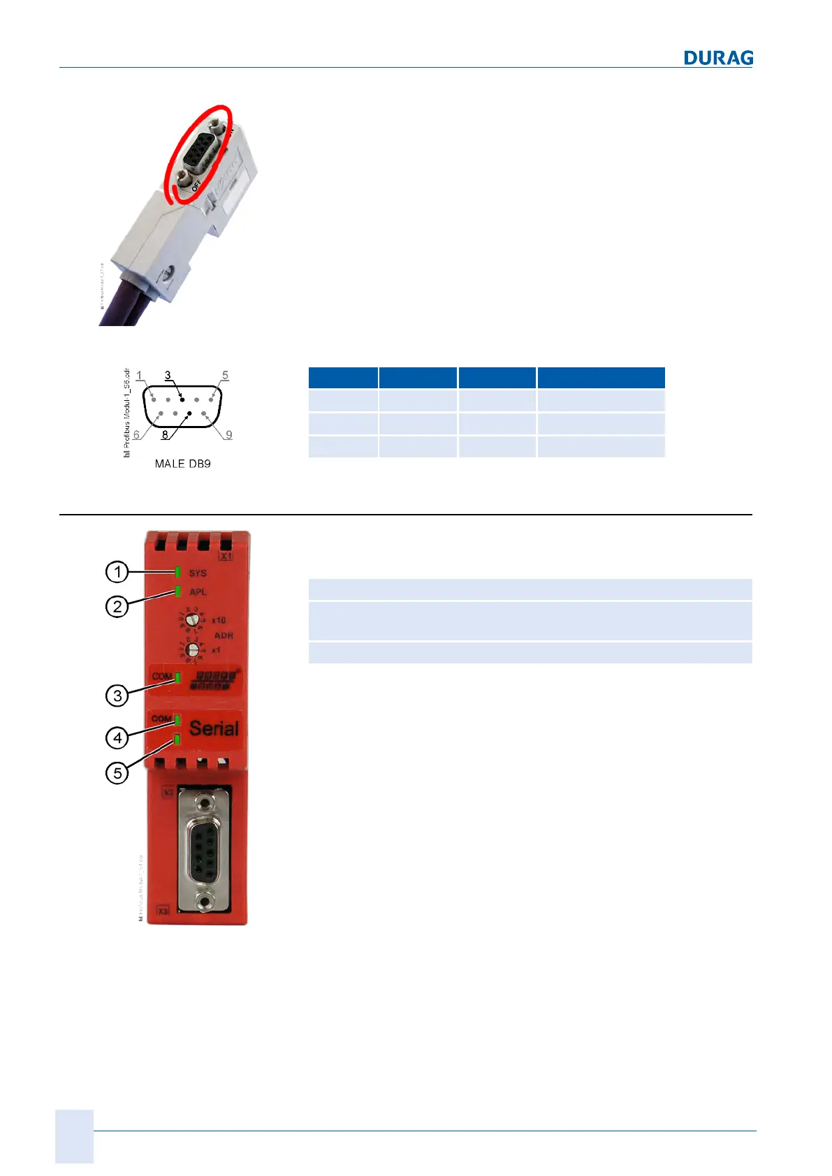
Fig.4.20: Profibus
sub-D-plug connector
The 9-pole sub-D plug connector for the internal Profibus plug
(see figure on the left) can be used for diagnostic purposes.
Connector Cable Colour Comment
3
A green Data cable A
8
B red Data cable B
Screen Screen Screen Cable screen
Table4.17: Profibus sub-D plug connector pin assignment
4.3.7.3 LEDs
In the Profibus module, LEDs for information are installed across
3 different areas (see figure on left).
1
System LED 1
2
System LED 2
3
Field bus LED
4
Internal communications
LED
5
(not used)
Table4.18: LEDs in the Profibus MD module
The LED displays have the following meaning:

 Loading...