10 | Channel setup menu 4
D-ISC 100 x xx2
99
Menu: 4.1.1
Status: S1.3:Normal measurement
D-ISC 100 (D)
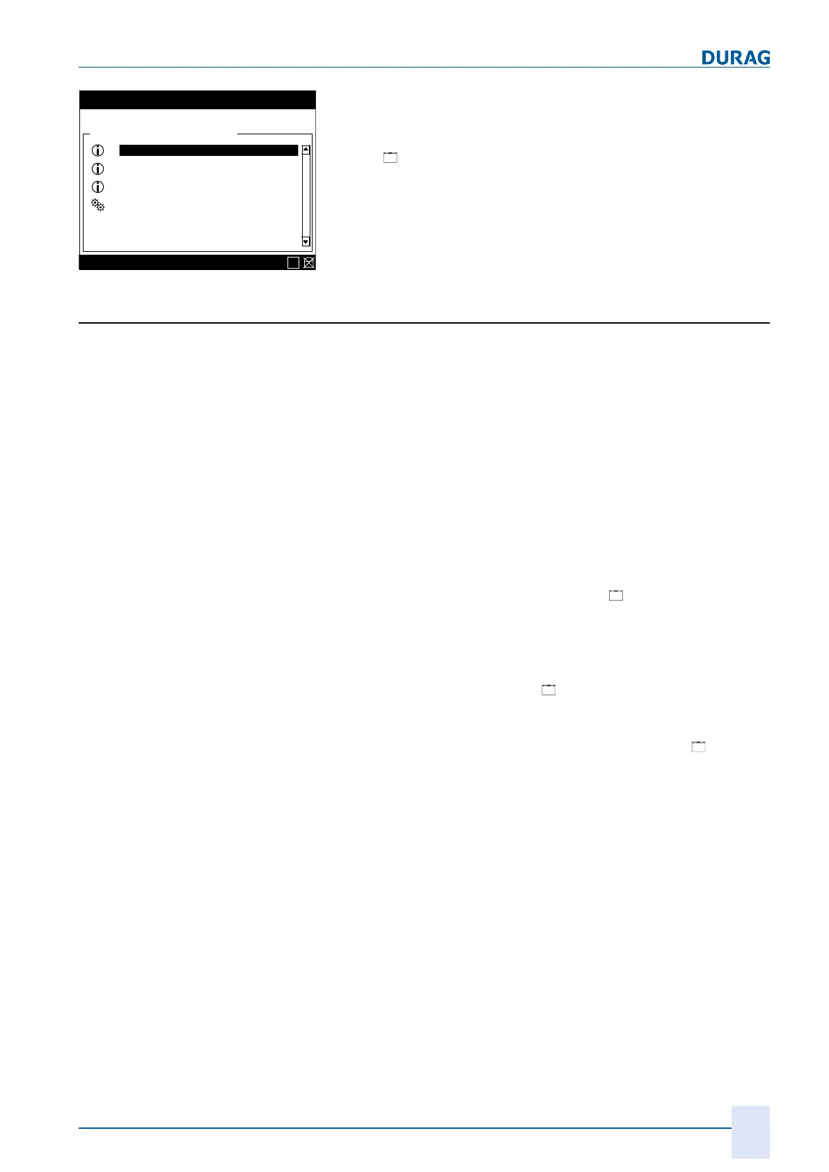
\\Menu\Channel setup\D-ISC 100 (D)
Device status
Specific parameter
Messages
Device status extended
Functions
E
Fig.10.5: Device status D‑ISC100
A detailed analysis of the status (e.g. for troubleshooting) can
then be carried out via the "Status" and "Messages" menus in
the menus for the individual system components, or alternatively
via the "
Device status extended" menu.
10.1.2 [Device status extended] D‑ISC 100 (D)
Sensor S1
(also S2 – S8)
Status of the sensor channel (e.g. S1) from the perspective of
the D‑ISC100:
● The D‑ISC100 Universal control unit can work with various
different DURAG sensors. The number of the connected
sensors can vary. The connections are made via the DURAG
Modbus. Sensors within a bus system may be replaced by
sensors that supply completely different measured values
(e.g. opacity instead of volumetric flow).
As a result, it is necessary to constantly monitor and signal
the status of the individual sensor channels.
● Example:
○
For maintenance purposes, a sensor has been disconnec-
ted from the D‑ISC100/DURAG Modbus-> Loss of commu-
nication with the sensor. ->Status: [
Offline]
○
Maintenance work has resulted in another sensor (with the
same DURAG Modbus address) being connected to the
D‑ISC100/DURAG Modbus -> the other sensor is deliver-
ing measured values which are incompatible with the con-
figured sensor. ->Status:
Other device online]
○
For maintenance purposes, a sensor has been disconnec-
ted from the D‑ISC100/DURAG Modbus
No sensor is initially registered there. ->Status:
Not
available
● The (actual) status of the sensor can be found in the channel
menu for the sensor.
Modul M1
(also M2 – M4)
Status of the module channel (e.g. M1) from the perspective of
the D‑ISC100:
● The D‑ISC100 can work with various different expansion
modules. The number of the connected modules can vary.
The connections are made via the DISC Modbus. Modules
within the module bus system may be replaced by modules
that have completely different functions and also supply differ-
ent data.
As a result, it is necessary to constantly monitor and signal
the status of the individual module channels.
● Example:
 Loading...