10 | Channel setup menu 4
106
D-ISC 100 x xx2
Target:
Status: S1.3:Normal measurement
Menu: 4.2.S1.6
S1:D-R 220
Status
Specific parameter
Assign measuring values
Functions
Common parameter
Messages
\\Channel setup\Sensor (S)\S1
E
Fig.10.18: Channel menu S1
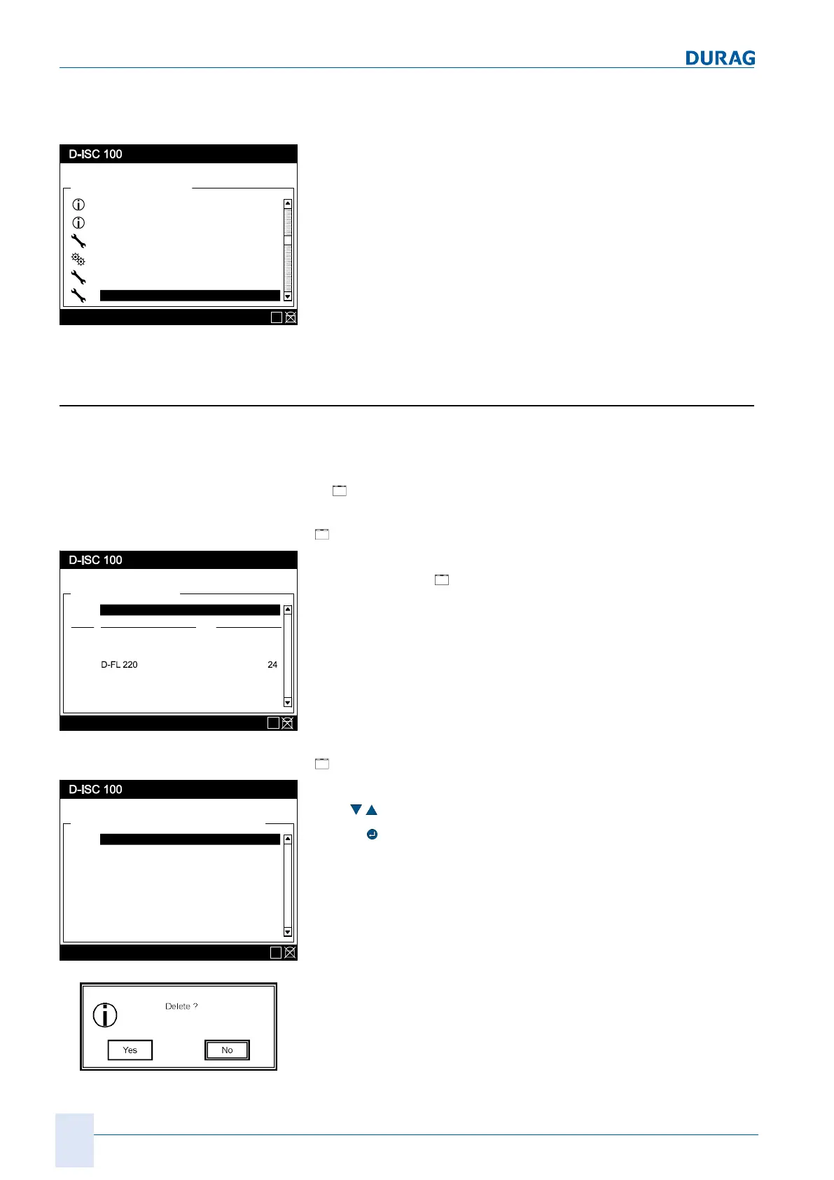
10.3.1 [Sx add/remove sensor]
● List of all sensor locations (S1..S8)
● The device name and the Modbus address for the device is
displayed at assigned sensor locations.
●
"Not assigned" is displayed at unassigned sensor loca-
tions.
Adding an Sx sensor:
[
Add sensor]
Sensor (S)
Status: S1.3:Normal measurement
Menu: 4.2.1
Add / remove sensor Addr
Specific parameter
D-R 220 22
S1
S2
Sx
\\Channel setup\Sensor (S)
E
Fig.10.19: Sensor menu
Additional sensors can be added to the system in the first line of
the sensor menu (
Add/remove sensor).
See also 15.7 Example: Adding a sensor [}165].
Remove Sx sensor:
[
Remove sensor]
Add / remove sensor
Status: S1.3:Normal measurement
Menu: 4.2.1.S1
D-R 220 22
Specific parameter
S1
not assigned
S3
\\Channel setup\Sensor (S)\Add / remove sensor
D-FL 220 24
S2
not assigned
S4
not assigned
S5
not assigned
S6
E
Fig.10.20: Remove sensor
To remove a sensor, select it from the list by using the arrow
keys (
) to move the black bar to the desired entry.
Use the
key to select the device for removal.
Before it is deleted from the system, a confirmation prompt is dis-
played, giving the opportunity to abort the process.
 Loading...