10 | Channel setup menu 4
D-ISC 100 x xx2
125
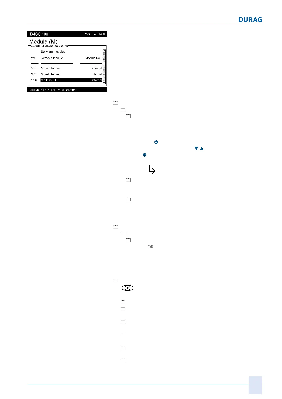
Fig.10.29: Module list
The "Modbus RTU" module will then be entered into the module
list (see figure on the left), from where it can be configured:
Specific parameters
(4.3.NS0.1)
[
Specific parameter]
● [
NS0 setup]
○
[
Modbus address]:
Modbus server address of the D‑ISC100 (default: 20)
○
Baud rate:
Selection of the speed of communication (default: 19200)
Pressing the
key in this line opens the Baud rate for ad-
justment. Use the arrow keys (
) to make the selection
and the
key to confirm.
The same selection can also be made in the following line
(after the
symbol).
○
[
Settings]:
Selection of the parity and the number of stop bits (default:
none / 1)
○
[
Termination]:
Enabling/disabling the bus termination of the D‑ISC100.
Termination must be enabled if the D‑ISC100 is located at
the end of a bus; otherwise it must be disabled.
Setup (4.3.NS0.2)
[
Setup]
● [
Common]
○
[
Customer name]
Press the
…
A user-specific name can be entered here for the respect-
ive sensor.
This name is then displayed in the measured value / status
display behind the sensor name.
Information (4.3.NS0.3)
[
Information]
The
symbol means:
the information in this line is read-only here!
● [
Device]
● [
Description]
●
[ Device description revision common]
●
[ Device description revision specific]
●
[ Device protocol revision common]
●
[ Device protocol revision specific]

 Loading...