15 | Examples of settings
174
D-ISC 100 x xx2
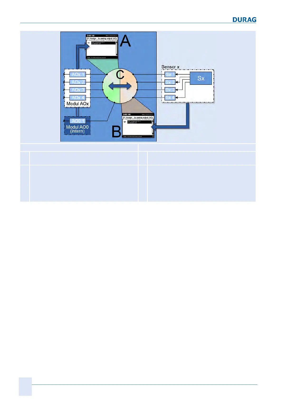
Method A Method B
A
Configuration of the analogue output via the
module configuration (M)
B
Configuration of the analogue output via the
sensor configuration (S)
C
Any link from the analogue outputs of the modules
AOx1 … AOx4 to the channels of sensors Sx.1 …
Sx4;
multiple assignment of an analogue output to vari-
ous sensor channels is not
permissible and not possible.
C
Any link from the channels of measuring device
Sx.1 … Sx4 to the analogue outputs of modules
AOx1 … AOx4; multiple assignment of a sensor
channel to various analogue outputs is possible.
Table15.3: Setting methods
Another option for the assignment is via the measuring device
configuration (methodB). In this case a sensor, or more pre-
cisely a measurement channel for the sensor, is assigned to one
(or also several) current output(s).
The options for the settings are shown in [}173]. MethodA is
the configuration of the analogue output via the configuration of
the module. MethodB shows the configuration of the analogue
output via the configuration of the sensor (measurement chan-
nel). C shows the linking options between the sensor channel
(Sx) and the analogue output (AOx). Each point on the left hand
side of the circle can be linked to any point on the right hand
side, and vice versa.
Method A
Assignment of the measurement channel (sensor) to the ana-
logue output
The keypad and menu can be used to select the sensor (S) and
one of its four measurement channels (S1.1 … S1.4), whose out-
put value is to be assigned to the D‑ISC100 current output.
For the individual steps, proceed in accordance with the
D‑ISC100 menu path (for an explanation of this, see Section7.1
Navigation guide within this manual [}79]). Comments on the
settings are included in the appropriate text where necessary.

 Loading...