4 | Installation and commissioning
D-ISC 100 x xx2
37
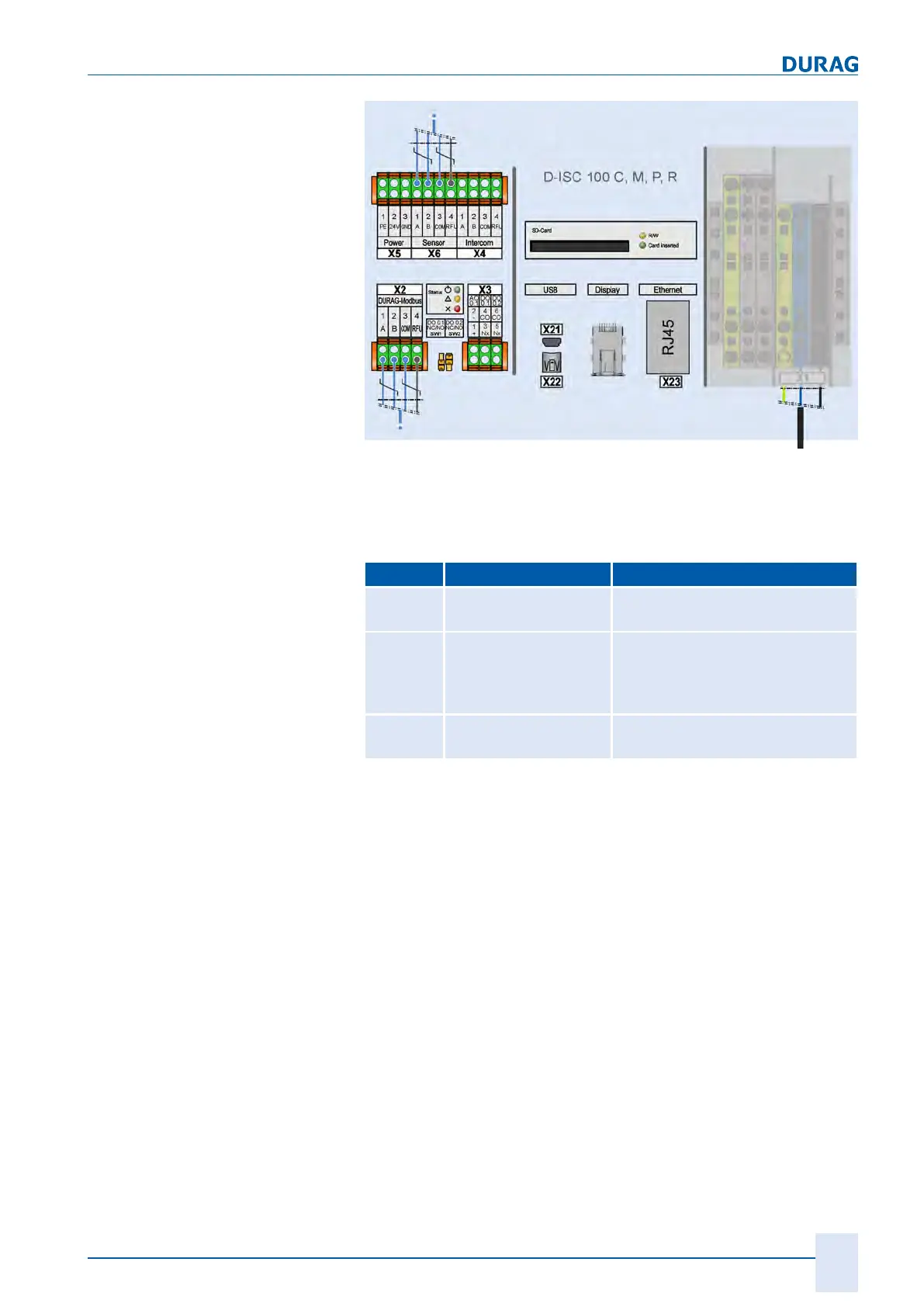
Fig.4.4: Wiring diagrams for the D-ISC 100 C, M, P, R bus cables
(RFU: Reserved for further use)
Connector descriptions can be found in the following table.
Connector Description Comments
X6 Sensor–Modbus
(Modbus–master)
Connection of a sensor or an up-
stream D‑ISC100*.
X2 Durag–Modbus
(Modbus–slave)
Only available with Modbus RTU–
slave expansion module. Connec-
tion of an evaluation system or a
downstream D‑ISC100*.
X23 Ethernet
(Modbus TCP server)
Only available with Modbus TCP
expansion module.
*See also:
● 4.2.5 Sensor network bus architecture (one D-ISC 100) [}41]
● 4.2.6 Sensor network bus architecture (multiple D-ISC 100)
[}43].
D‑ISC100 bus connection
(with M12 connectors)
The bus connections can in principle be established via pre-as-
sembled cables with M12 connectors in accordance with EN
61076-2-101. The following pin assignments apply for the differ-
ent bus systems:

 Loading...