5 | Basic operation of the D-ISC 100
74
D-ISC 100 x xx2
Component Function Status display Measurement display
Software module Media conditions (MC0) X
Software module Modbus TCP (NE0) X
Software module Modbus RTU (NS0) X
Expansion module Analogue output (AOm)* X
Expansion module Analogue input (AIm)* X
Expansion module Digital output (DOm)* X
Expansion module Digital input (DIm)* X
Expansion module Profibus DP - -
Table5.6: Measured value/status display
_______________
* identification in the display, e.g. in the window title (see [}69]
for an explanation of terms)
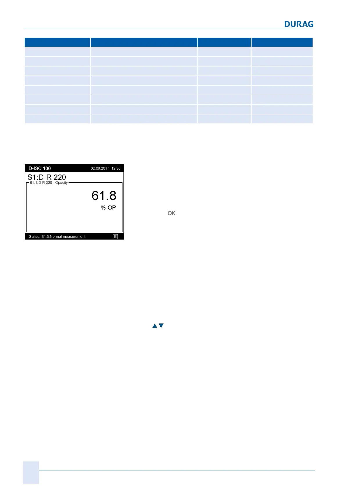
Fig.5.10: Example measured value
and status display
Every measured value and status display contains a
header bar
:
Device name (D−ISC100, left) and system date / time (right).
Every measured value and status display contains a
status bar
:
Status – messages about the status display (D) are continuously
displayed in this line.
Pressing the (
) key takes you directly back to the channel
menu for the current channel. In this menu, you can access addi-
tional information about the channel in question, adjust the set-
tings and carry out functions.
Parameters for external devices and expansion modules are
saved in the respective devices/modules (not in the D-ISC 100).
Status display (D)
● Lists the most important status reports from all the channels
of the overall system
● Each status is prefixed by the respective channel identifier (D,
S1, …)
● The list may be longer than the display can show. This can be
identified by the scroll
bar (which will only be shown in this case); use the cursor
keys
to scroll.
Measurement display (MXo)
Compilation of a measured value display from different channels
by the user
(selectable source channels: Sn, SXp, MC0)
provides a quick overview of a system's key measured values at
a glance (see Section 10.4.1.4 [Mixed channel] (MX1...2) [}116]).
 Loading...