12 | Messages/error elimination
D-ISC 100 x xx2
145
No./
colour(s)
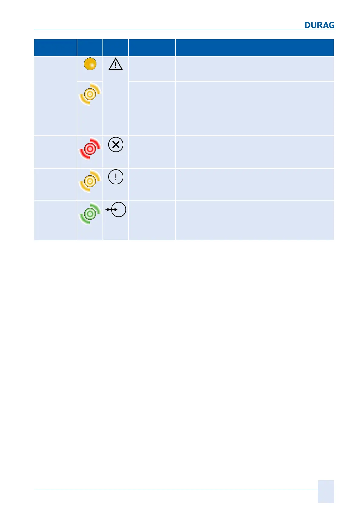
LED Symbol Status Meaning
32
yellow
On ● Maintenance status for the D‑ISC100 or a connected
sensor
(no valid measured value is output during this period)
Flashing ● in 1-second cycles
(cycle ratio 50/50)
● D‑ISC100 or a connected sensor/module has saved a
message (warning/information).
(A valid measured value is output during this time, but
the device function may be restricted due to an in-
ternal error)
33
red
Flashing ● in 1-second cycles
(cycle ratio 50/50)
● Error/fault in the D‑ISC100 or a connected sensor/
module
34
yellow
Flashing ● Bus (data) error
● Flashes in synchronism (at the end of the receipt
frame) with the green LED (5) when a defective
DURAG Modbus frame is being received.
35
green
Flashing ● Bus active
● Flashes when a DURAG Modbus frame is being trans-
mitted or received.
● Flashes in synchronism with the yellow LED (4) when
a defective DURAG Modbus frame is being received.
Table12.9: Flash code meaning
 Loading...