12 | Messages/error elimination
144
D-ISC 100 x xx2
Code Message Measures
[224] [Hardware fault] 1. Restart the device
2. Replace the main board
Table12.6: Messages by the analogue input expansion module
Code Message Measures
Critical fault (specific)
[224] [Hardware fault] 1. Restart the device
2. Replace the main board
Table12.7: Messages by the analogue output expansion module
Code Message Measures
Critical fault (specific)
[224] [Hardware fault] 1. Restart the device
2. Replace the main board
Table12.8: Messages by the digital output expansion module
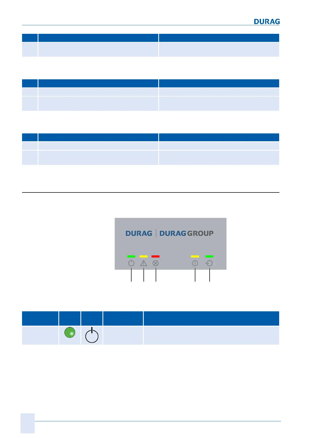
12.8 Reports via the LEDs
There are five LEDs in the area above the display. These indic-
ate the current operating status.
Fig.12.1: LED assignment in the D‑ISC100 C, M, P, R
No./
colour(s)
LED Symbol Status Meaning
31
green
On ● Ready for operation / in operation
 Loading...