15 | Examples of settings
D-ISC 100 x xx2
165
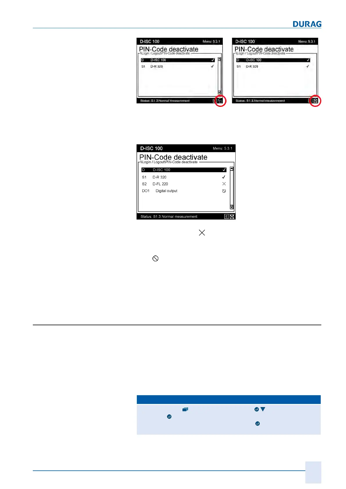
Fig.15.14: Deactivating the PIN lock II
The display of the PIN protection status (see figure above;
circled section in the status line) will change after the D‑ISC100
has reported deactivation of the PIN protection.
Fig.15.15: Deactivating the PIN lock III
There will be a cross (
) next to all of the devices for which the
PIN code has not been deactivated (see figure above for D-
FL220).
If the
symbol is shown, then the device does not have any in-
ternal PIN protection (e.g. modules).
If the PIN code has not been changed (deactivated) successfully,
the device will nevertheless continue to be protected against any
unintentional changes. The old, previous PIN code will remain
valid!
15.7 Example: Adding a sensor
When a sensor is connected to the D‑ISC100 for the first time, it
must be "registered" to the system. This is done using the
keypad and the display.
For the individual steps, proceed in accordance with the
D‑ISC100 menu path (for an explanation of this, see Section7.1
Navigation guide within this manual [}79]). Comments on the
settings are included in the appropriate text where necessary.
D‑ISC100 menu path:
Standard display Channel Setup (menu3) Sensor (S)
(menu3.2)
(Sx)Add/removeSensor Addr. (MENU 3.2.1) =Add/removesensor
MENU 3.2.1
 Loading...