15 | Examples of settings
D-ISC 100 x xx2
189
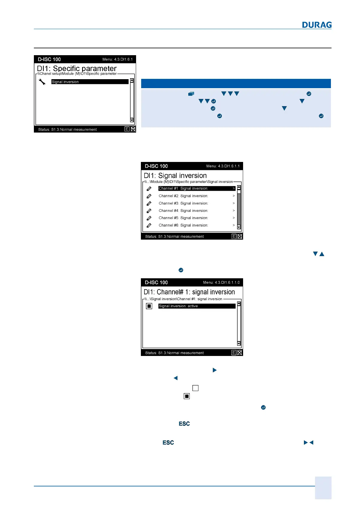
15.12.1 Example: Signal inversion setup (digital inputs)
Fig.15.57: Digital input
specific parameter
If required, the signal can also be inverted for digital inputs.
Proceed as follows:
D‑ISC100 menu path:
Standard display (menu1) Channelsetup (menu4) Chan-
nelsetup (menu4.1)
Modules(M) (menu4.3.1) e.g. (4x) Di-
gital input (menu4.3.DI1)
Status (menu4.3.DI1.1) (5x) Specific
parameter (menu4.3.DI1.6)
Signal inversion (menu4.3.DI1.6.1)
=MENU4.3.DI1.6.1.1
After the specific parameters of the digital input has been called
up, the desired channel can be selected from a list.
Fig.15.58: Inverting the signal
There are 8 channels to choose from. Use the arrow keys (
)
to select a channel and load the selection in the system by
pressing the
key.
Fig.15.59: Activating signal inversion
Use the right arrow key (
) to activate the inversion; use the left
arrow key (
) to deactivate it.
An empty square
means "not active (not selected)";
a solid square
means "active (selected)".
If you exit the menu item by pressing the
key, the setting will
be loaded and saved in the system. If you exit the menu item by
pressing the
key, the setting will not be loaded.
To check the setting, return to the digital input display by press-
ing the
key multiple times as well as the arrow key ( ):
 Loading...