15 | Examples of settings
198
D-ISC 100 x xx2
Step 3
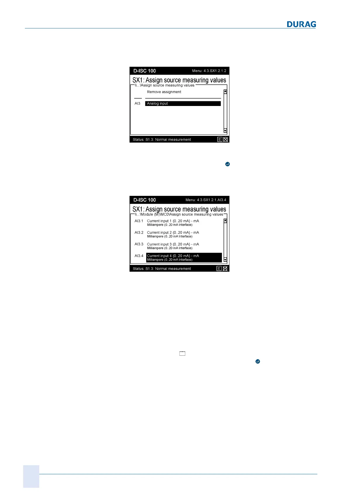
Fig.15.74: Assign source 2
Select the analogue input from the list of possible sources. Con-
firm the selection by pressing the
key. In our example, the ana-
logue input module is in the third position in the list (see Section
10.4.3 Modules (M) (expansion module, hardware) [}126]); and
is therefore designated as AI3 (AnalogIn3).
Fig.15.75: Assign source 3
The analogue input module has 4 channels, to which different
sensors can be assigned depending on the system and the cur-
rent signal. First, familiarise yourself with which of your sensors
have been connected to which analogue input.
Step 4
One of these connected sensors (let us assume this to be a func-
tionally installed temperature sensor) now has to be assigned to
a channel of the [
External sensor] software module. In our ex-
ample, we select AI3.4 and confirm with the
key.
 Loading...