15 | Examples of settings
D-ISC 100 x xx2
199
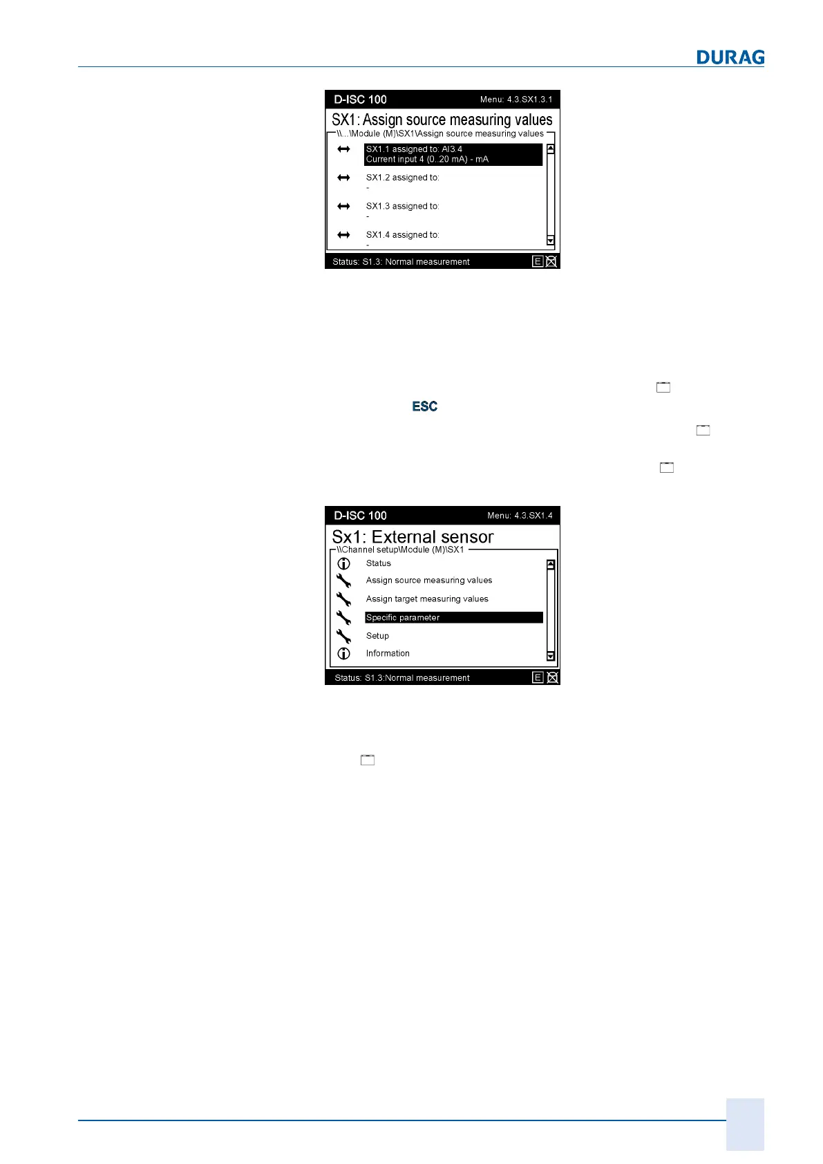
Fig.15.76: Display the assigned source
The display now shows the assigned analogue input for the Ex-
ternal sensor software module.
Step 5
Go back to the [Assign source measuring values
] display by
pressing the
key on the keypad.
(In special application cases, a target measuring value
can
now also be assigned [Assign target measuring value]. This
would make it possible to display the value on an
analogue
output.)
Fig.15.77: Assigning specific parameters
Step 6
The [
specific parameters]
must
now
be defined for each of the
used
external sensor channels e.g. SX1.1 ... SX1.4. These in-
clude limit values, signal range and the unit display (amperes,
hectopascals, metre, etc.) in which the measured value is
presented. The specific parameters are described in more detail
in Section 10.4.1.5 [External sensors] (SX1...2) [}117].
Assign the desired parameters. It may be useful to take the rel-
evant values from the
data sheet
of the
connected sensor
. This
avoids misinterpretations in the measured value output.
After these have been assigned, the measured value from the
External sensor module will be available in the D−ISC100 meas-
ured value display (see also Section 15.9 Examples: Selection of
the displayed data [}170]).
 Loading...