4 | Installation and commissioning
D-ISC 100 x xx2
39
Expansion module Profibus DP
Quantity Name Type Pos*
1 M12 B-coded male 1
1 M12 B-coded female 2
The "sensor" X6 connection is usually connected to the factory-
installed sensor connection cable. With the D‑ISC100M and
D‑ISC100P, the connection can also be guided out of the hous-
ing with an M12 connector **(must be ordered separately):
X6: Sensor (Modbus Master)
Quantity Name Type Pos*
1 M12 A-coded male 4
1 Y adapter
M12 A-coded
female
→**male/female
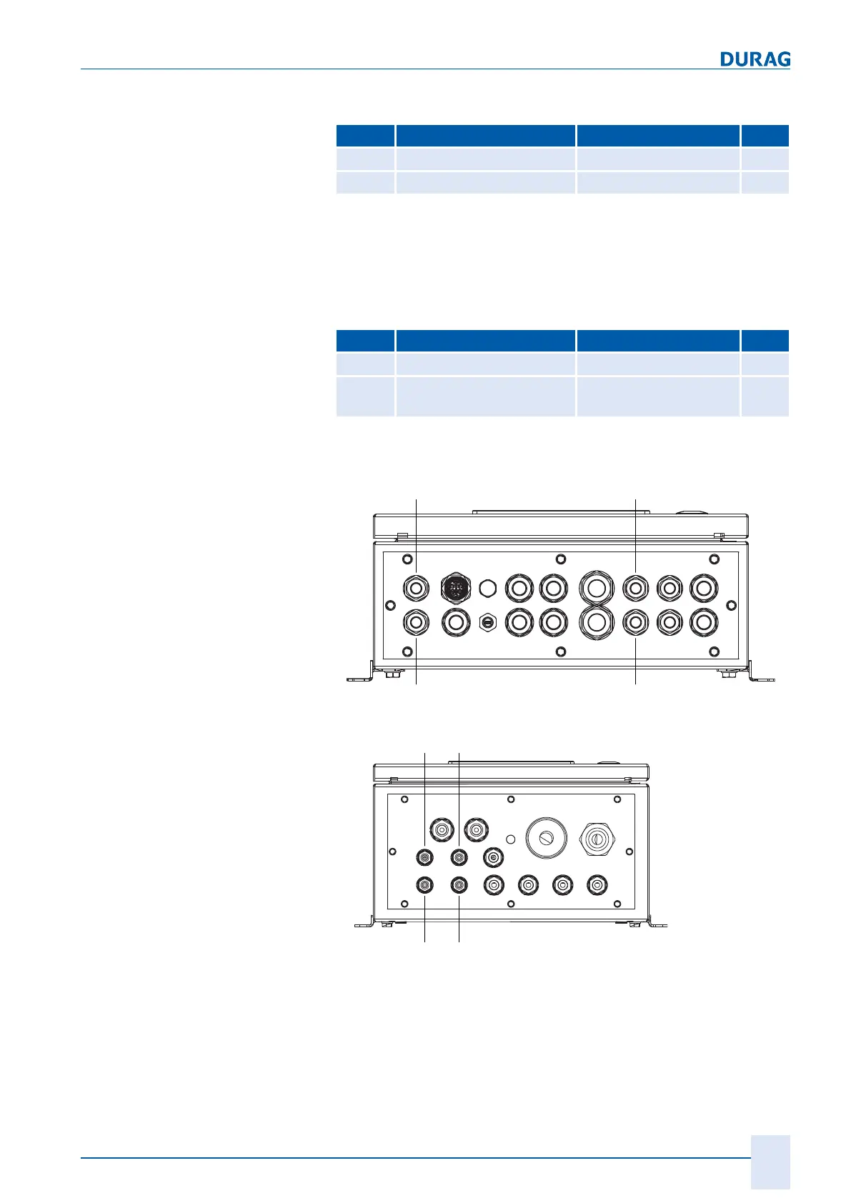
* Pos. see Fig.4.5 to Fig.4.7
Position of the connector in the
housing
Fig.4.5: Position of the connector with D‑ISC100M
Fig.4.6: Position of the connector with D‑ISC100P
 Loading...