Installation
04/10 MN04020001Z-EN
34
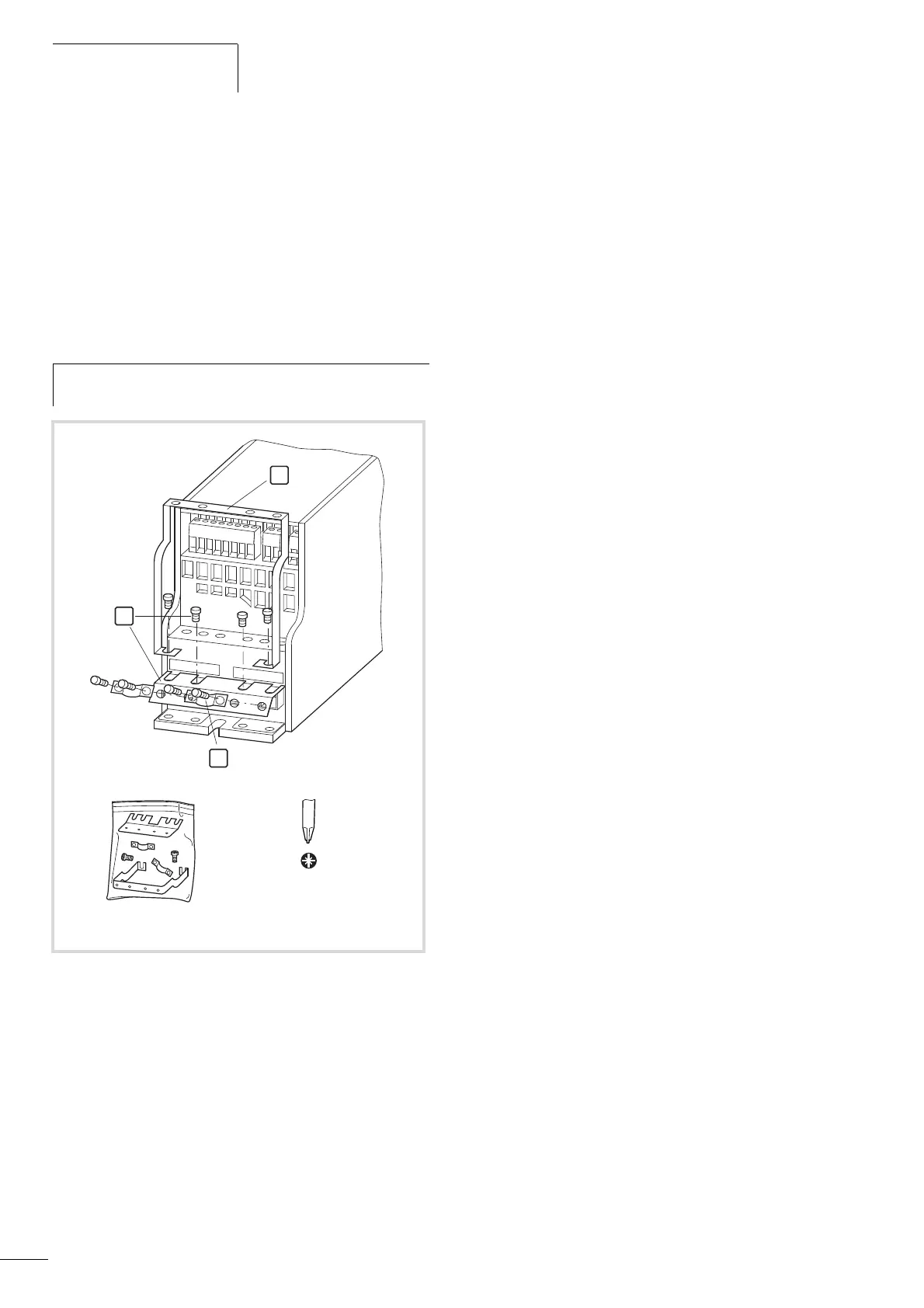
Cable flange plate (Accessories)
The M-Max
TM
is supplied with a cable routing plate and brackets.
These enable you to arrange the connection cables as required on
the frequency inverter and fasten the shielded cables in
accordance with EMC requirements.
First, install the cable clamp plate for the connection lines in the
power section [1] and then the cable clamping plate [2] for the
control lines. The required installation screws (M4) included as
standard.
[3] = gland plates in the power section.
h
Mount the cable routing plate before the electrical
installation.
PZ2
1.3 Nm
(11.5 lb-in)
Figure 25: Mounting the cable routing plate and the brackets
L1 L2/N L3
U/T1
V/T2
W/T3
1
2
3
 Loading...


