04/10 MN04020001Z-EN
Electrical Installation
39
Prevent the shielding from becoming unbraided, i.e. by pushing
the separated plastic covering over the end of the shielding or with
a rubber grommet on the end of the shielding. As an alternative,
in addition to a broad area cable clip, you can also twist the
shielding braid at the end and connect to protective ground with
a cable clip. To prevent EMC disturbance, this twisted shielding
connection should be made as short as possible (see figure 32).
Shielded, four-wire cable is recommended for the motor cables.
The green-yellow line of this cable connects the protective ground
connections from the motor and the frequency inverter and
therefore minimizes the equalizing current loads on the shielding
braid.
Twisted shielding braid should be connected with a ring cable
terminal (see figure 29, page 38) on PES.
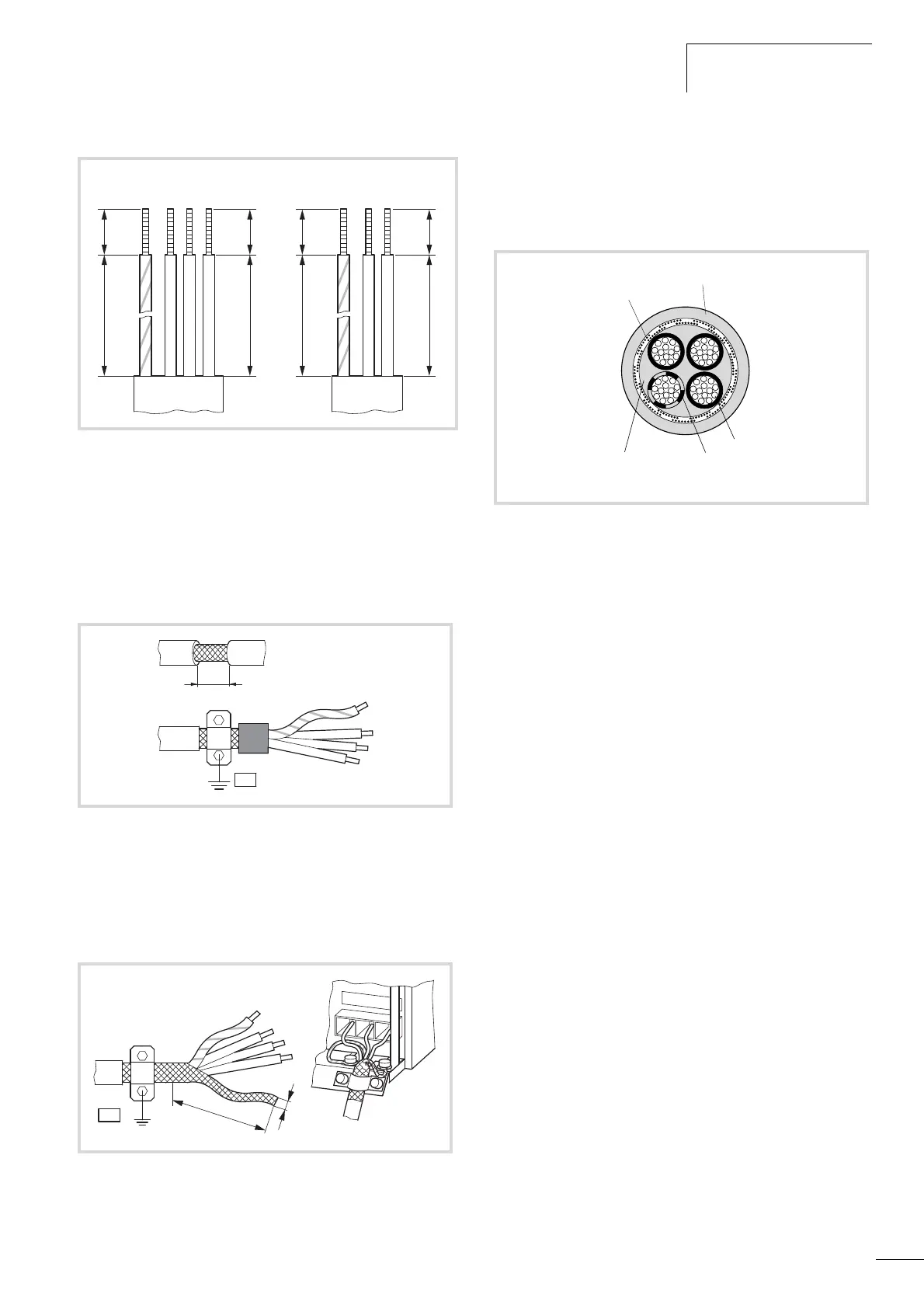
The following figure shows the construction of a four-wire,
shielded motor line (recommended specifications).
If there are additional subassemblies in a motor circuit (i.e. motor
contactors, relays, motor reactor, sinusoidal filters or terminals),
interrupt the shielding of the motor cable in the vicinity of these
subassemblies. Connect this over a broad surface area with the
mounting plate (PES). Free or non-shielded connection cables
should not be any longer than about 300 mm.
Figure 30: Connection in power section
Figure 31: Screened connection cable
Figure 32: Connection with twisted cable shielding
Recommended value for twisted cable shielding:
b f 1/5 a
8 mm
(0.314“)
20 mm
(0.787“)
8 mm
(0.314“)
35 mm
(1.378“)
PE L1 L2 L3
PE U V W
8 mm
(0.314“)
20 mm
(0.787“)
8 mm
(0.314“)
35 mm
(1.378“)
PE R+ R-
Figure 33: Four-core shielded motor supply cable
a Cu shield braid
b PVC outer sheath
c Drain wire (copper strands)
d PVC core insulation, 3 x black, 1 x green–yellow
e Textile and PVC fillers
 Loading...


