04/10 MN04020001Z-EN
Electrical Installation
47
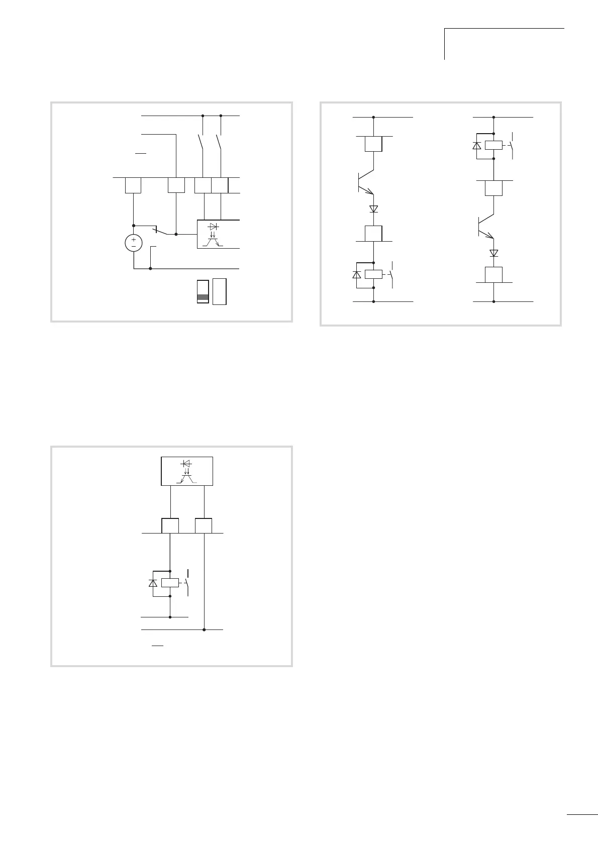
Digital output (Transistor)
The transistor output (control signal terminal 13, DO-) can be
supplied with the internal control voltage (+24 V) via control
signal terminal 20 (DO+) or with an external DC voltage of up to
+48 V. The permissible residual ripple must be less than
±5 % DU
a
/U
a
. The maximum permissible load current is 50 mA.
The parameter assignment is described in Section “Digital output
(P5)”, page 84.
Figure 47: Digital inputs with external supply voltage (negative logic,
Sink type)
Figure 48: Digital output DO and connection examples (coupling
relay with freewheeling diode:
ETS4-VS3; Item No. 083094)
789
DI1
DI2
DI_COM
6
< 50 mA
+24 V Out
0 V
+24 V
(
F g 5 %
)
Du
U
a
a
S1
S1 =LOGIC-
(Sink type)
LOGIC
- +
Ready
< 50 mA
DO-
DO+
13 20
+
+ 24 V
(
F g 5 %
)
Du
U
a
a
0 V
Figure 49: Connection example and operation of DO in Source and
Sink type
+ 24 V
0 V
< 50 mA
20
13
DO-
DO+
Source type
+ 24 V
0 V
< 50 mA
20
13
DO-
DO+
Sink type
 Loading...


