Installation
04/10 MN04020001Z-EN
48
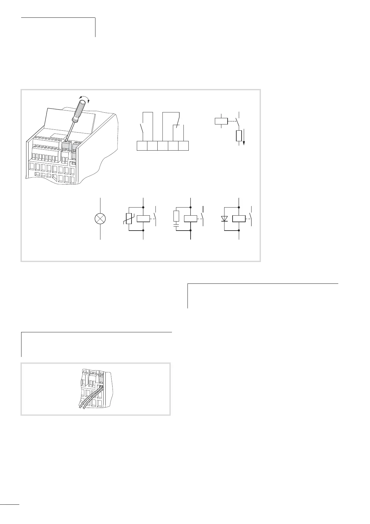
Digital outputs (relays)
The following figure shows the arrangement of the connection
terminals for both relay contacts.
The two relay outputs (control signal terminals 22 to 26) enable
the frequency inverter to generate galvanically isolated feedback
signals in control circuits with other potentials:
• maximum switching capacity: 250 V DC, 0.4 A (DC voltage),
• maximum switching capacity: 250 V AC, 2 A (AC voltage).
The functions for which parameters can be defined are described
in Section “Digital output (P5)”, page 84.
The factory setting causes N/O contact R13/R14 (control signal
terminal 22/23) of relay RO1 to indicate operation (RUN).
N/O contact R21/R24 (control signal terminal 25/26) of relay RO2
indicates a detected fault (ERROR = FAULT).
The functions for which parameters can be defined for both relays
RO1 and RO2 are described in Section “Digital output (P5)”,
page 84.
250 V h : F 2A
250 V H : F 0.4 A
Figure 50: Relay outputs with connection examples, Control relay with suppressor circuit
2322
24 2625
R13
R14
R21
R22
R24
Error
Run
AC
DC
AC
Varistor
(+)
(
-
)
DC
Diode
AC
RC filter
h
With voltages greater than 48 V, you should fasten the
connection cables of the relay in the opening on the right
(housing).
Figure 51: Fixed connection cables at U > 48 V (relay)
h
If the supply voltage of the frequency inverter is switched
off upon the occurrence of an error message, the N/O
R21/R24 opens again (relay drops out).
 Loading...


