04/10 MN04020001Z-EN
Electrical Installation
49
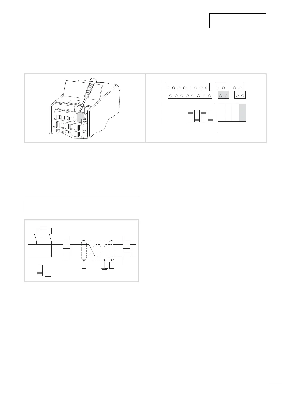
Serial interface A-B
The following figure shows the connections of the serial interface
and the position of the micro-switch for the bus termination
resistor.
The two control signal terminals A and B enable the connection of
a shielded RS485 twisted-pair cable.
The bus terminating resistor required at the end of a data cable is
integrated in the frequency inverter and can be connected via
microswitch S4.
The parameter definition of the serial interface is described in
chapter ”Serial interface (Modbus RTU)”.
Figure 52: Connection terminals of the serial interface and microswitch
S4 (bus terminating resistor)
12367
8
9
10 25 24
4 5 13 14 15 16 18 20 22 23 26
AI2
DO-GND
DI4 DI5 DI6 AO DO+
R13
R14 - R24
+
10V AI1 GND
24V
DI-C
DI1 DI2 DI3 A B R21 R22
LOGIC
- +
AI 1
V mA
AI 2
V mA
RS 485
- term.
S4 = RS485 (-)
h
The network cable must have a bus termination resistor
(120
O) connected at each physical end to prevent
reflections and the resulting transmission faults.
Figure 53: Two-wire RS485 connection
(Slave = M-Max
TM
frequency inverter)
A
B
A
B
PES
PES
Slave Master
RS485
Modbus (RTU)
S4
120 O
RS485
- term
 Loading...


