B580-65-880 Issue G
Page 28 © Edwards Limited 2008. All rights reserved.
Edwards and the Edwards logo are trademarks of Edwards Limited.
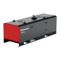
ACX air-cooler
3.3 Installation
3.3.1 Unpack and inspect
Remove all packing materials and protective covers and check the ACX air-cooler.
If the ACX air-cooler is damaged, notify your supplier and the carrier in writing within three days; state the Item
Number of the ACX air-cooler together with your order number and your supplier's invoice number. Retain all packing
materials for inspection. Do not use the ACX air-cooler if it is damaged.
3.3.2 Side (or radial) mounting
1. Switch off the pump, isolate the pump controller from the electrical supply (on an EXT DX pump, isolate the
podule from the electrical supply), and wait until the pump has stopped rotating.
2. Continue at Step 3 in the appropriate EXT75DX pumps, EXTPX pumps, EXT555H pumps or Other pumps
procedure below, depending on the type of your pump.
3.3.2.1 EXT75DX pumps
3. Unscrew the rubber pump mounting feet.
4. Fit the ACX75 air-cooler mounting bracket to the base of the pump, and refit the mounting feet to secure the
mounting bracket in place.
3.3.2.2 EXTPX pumps
Refer to Figure 12 and 13.
3. Unscrew the rubber pump mounting feet.
4. The ACX400 radial cooling kits can be attached to the EXTPX pumps via fixing holes on the base of the product
using 5 x M8 screws (supplied). To ensure that the radial cooling kit works most effectively it is recommended
that the fan should be placed directly opposite the booster port position. This ensures adequate cooling of the
EXDC controller.
3.3.2.3 EXT555H pumps
To base-mount the air-cooler:
3. Refer to Figure 20. Unscrew the rubber pump mounting feet (4).
4. Fit the mounting bracket of the ACX555 air-cooler (2) to the pump-base (6) in the most suitable orientation.
5. Use two M8 x 25 fixing screws (3) and two of the pump mounting feet (4) to secure the mounting bracket in
place.
6. Use two spacers (5) and refit the other two pump mounting feet.
To flange-mount the air-cooler, do not refit the pump mounting feet, but use four screws to secure the air-cooler to
the pump.