© Edwards Limited 2008. All rights reserved. Page 51
Edwards and the Edwards logo are trademarks of Edwards Limited.
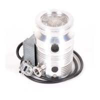
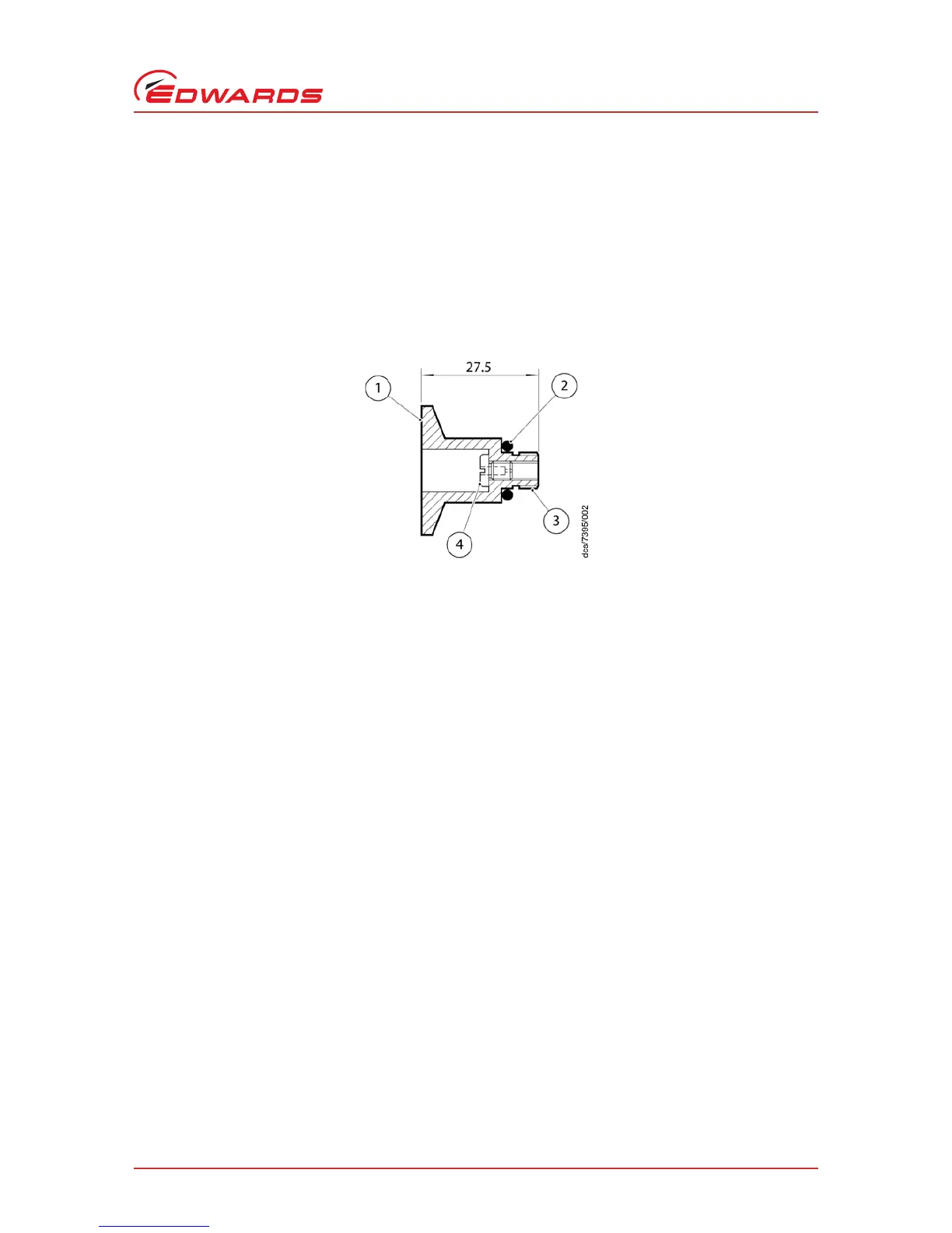
Vent-port adaptor
B580-65-880 Issue G
9 Vent-port adaptor
9.1 Description
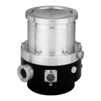
The 1/8 inch BSP(P) male to NW10 vent-port adaptor can be used to convert the 1/8 inch BSP(P) female vent port on
all EXT pumps to an NW10 flange. An alternative vent valve to the TAV 5/6 or a vent pipeline may then be fitted to
this flange. See Figure 29.
Figure 29 - Vent-port adaptor
The vent-port adaptor is supplied with a removable flow restrictor and an O-ring to seal the adaptor to the pump. It
is best suited to the following pump types:
z EXT75DX, EXT75iDX
z EXT255DX, EXT255iDX
z EXT255H, EXT255Hi
z EXT556H, EXT555H and EXT555H
E
z EXT406PX and EXTPX split flow
Also available is an extended vent-port adaptor which is intended for use with the split-flow turbo pumps where the
backing port is too close to the vent-port to allow the standard vent-port adaptor to be used. The extended vent-port
adaptor is supplied with an O-ring to seal to the pump, NW10 centering ring and NW10/16 clamping ring. Refer to
Figure 30.