INSTALLATION OF
THE DISPLAY UNIT IDT
-002
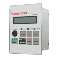
This LCD shows a pump’s operation state, rotational speed,
an error message, or other messages.
This connector is for serial communication with a PC with the
specified cable (optional accessory). That allows monitoring
an operating condition of an STP pump on a PC screen with
the monitor software, "STP-Link" (option accessory).
(Green LED) Illuminates during acceleration
(ACCELERATION state)
(Green LED) Illuminates during deceleration (BRAKE state)
This switch is for starting rotating an STP pump.
(It is valid only when an input operation port is set to display
unit connection port)
This switch is for stopping rotating an STP pump.
(It is valid only when an input operation port is set to display
unit connection port)
This switch is for make failures reset.
(It is valid only when an input operation port is set to display
unit connection port)
This switch can change the Abnormality/error displays and
settings.
This switch can select the settings. And that also can enter
the WARNING message display when “w” appears on the
“Operation Mode”.
Confirmation mode change function
Parameter set mode change function
(Press both of "UP" and "SELECT" switches simultaneously to
enter the Parameter Set Mode.)
Manual operation mode change function
(Press the "DOWN" and "SELECT" switches simultaneously to
enter Manual Operation Mode.)
Input operation port setting mode change function
(Press the "ENTER" and "SELECT" switches simultaneously
to enter Input Operation Port Setting Mode.)
Table 1 - iDT-002 front panel function
 Loading...