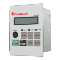
4.2 Power OFF
• Power Off an STP pump while connecting a communication cable to the STP-LINK connector
on the display unit iDT-002, then iDT-002 is also to be powered off automatically.
• While the STP pump is in a power-on state, disconnect the communication cable from the STP-
LINK connector, then the display unit iDT-002 is to be powered off automatically.
4.3 STP pump operation
CAUTION
DO NOT disconnect the communication cable during the operation mode. If the serial
communication time exceeds the serial communication time out set value during acceleration or
normal operation, the STP pump will stop. Refer to Section 5.2.5, "Serial communication time out
setting" in the STP pump Instruction Manual.
CAUTION
Read Section 4, "OPERATION" in the STP pump Instruction Manual carefully for operating the STP
pump.
This section shows how to start, stop, and reset an STP pump.
Refer to Section 4.3.1, "STP pump setting," for the setting of an STP pump.
4.3.1 STP pump setting
To enable operating an STP pump through the serial port, open the “PORT SELECT IN” input signal
of an STP pump (refer to Section 4.9, "Parallel port input/output signal" in the STP pump Instruction
Manual). Parallel ports included the “PORT SELECT IN” input signal and “PORT SELECT IN” input
signal pin numbers that need to open are different according to STP pump models (refer to Table 4).
Set “Input operation port setting” to the connector connected to a pump (refer to 4.7, “Parameter set
mode” and 4.9 "Input operation port set mode” or use “STP-link”).
iS1607
iS2207
iX457
iXU457
iXA3307
iXA4507
series
iXA2206
iXA3306
iXA4506
iX3006
series
(Except for
EtherCAT ver.)
iXA2206
iXA3306
iXA4506
iX3006
series
(EtherCAT ver.)
Parallel port included the “PORT
SELECT IN” input signal
Nothing
(No actions need)
“PORT SELECT IN” input signal
pin no. that need to open
Table 4 - Setting for “PORT SELECT IN” input

 Loading...