EasyManua.ls Logo

Edwards iDT-002

Edwards iDT-002
67 pages
To Next Page IconTo Next Page
To Previous Page IconTo Previous Page
Loading...
Display Unit iDT-002
MT-91E-A01-B
Page 17
INSTALLATION OF THE DISPLAY UNIT IDT
-002
3
X3
Connector
Pin No.
Signal
STP pump
X1
Connector
Pin No.
Remark
3
Communication RxD+
6
Use twisted-pair wire
7
Communication RxD-
7
4
Communication TxD+
2
Use twisted-pair wire
8
Communication TxD-
3
5
FG
4
1
0VA
5
Connect to the - output terminal (0 V) of
the DC power supply
6
+24v
1
Connect to the + output terminal (24 V) of
the DC power supply
2, 9
8, 9, 10
No connection allowed
Table 3 - iDT-002 X3 Connector pin layout
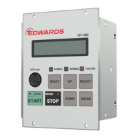
3.7 Attaching the display unit to a rack
The dimensions of the display unit iDT-002 front panel conform to EIA standards.
Therefore, this panel can be attached to the commercially available racks designed with EIA
standards.
Installation:
Attach the display unit iDT-002 front panel to a rack using the screw holes for the front panel.
Note: For the dimensions of the front panel, see Figure 2.
STP-Link
BRAK E
A CCE L .
S T O PS T A R T
NORMAL FAILURE
POWER
UP
DOWN ENTE R
SELECTRESET
Figure 10 - Screw holes position for securing to the rack
Note: When installing the power supply unit iPD-240-24V for the STP-iX457/iXU457 series (Display
Unit Integrated Power Supply) into a rack, refer to the iPD-240-24V instruction manual.

Table of Contents

Related product manuals