CAUTION
When operating connection/disconnection of the communication cable while the pump is in
operation, an appropriate enclosure or a barrier that cannot be removed without using a tool should
be provided around the STP pump to protect an operator from unexpected dangers.
4.1 Power ON
• After connecting a communication cable to the STP-LINK connector, power ON the STP pump
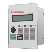
then automatically starts the display unit iDT-002.
• While an STP pump is in a power-on state, connect a communication cable to the STP-LINK
connector and then automatically start the display unit iDT-002.
4.1.1 LCD indication in power ON state
When a display unit iDT-002 is powered ON, the model and version of the display unit are displayed
on the LCD. After a few seconds, the display unit iDT-002 displays the pump operation state and
allows it to be controlled.
When a specific error of the display unit occurs, such as a communication error, an error message is
displayed on the LCD. Refer to Section 5, "TROUBLESHOOTING," for the contents of error
messages.
 Loading...