ILLUSTRATIONS
Figure Title Page
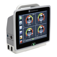
1 Display unit iDT-002 dimensions 4
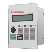
2 Front panel 6
3 Side panel and rear panel 9
4 Connecting to the STP pump (STP-iS1607/iS2207 series) 12
5 Connecting to the STP pump
(STP-iXA2206/iXA3306/iXA4506/iX3006 series) 12
6 Connecting to the STP pump (STP-iXA3307/iXA4507 series) 13
7 Communication cable 14
8 Connecting to the STP pump
(STP-iX457/iXU457 series [using iPD-240-24V]) 15
9 Connecting to the STP pump
(STP-iX457/iXU457 series [not using iPD-240-24V]) 16
10 Screw holes position for securing to the rack 17
11 Example of LCD indication in power ON state 19
12 Example of error message indication 24
13 Example of warning indication 25
14 Confirmation mode operation method (1/2) 29
15 Confirmation mode operation method (2/2) 30
16 Example of error record 31
17 Setting method (1/6) 40
18 Setting method (2/6) 41
19 Setting method (3/6) 42
20 Setting method (4/6) 43
21 Setting method (5/6) 44
22 Setting method (6/6) 45
23 Manual operation mode operation method 47
24 Input operation port setting mode operation method 49
 Loading...