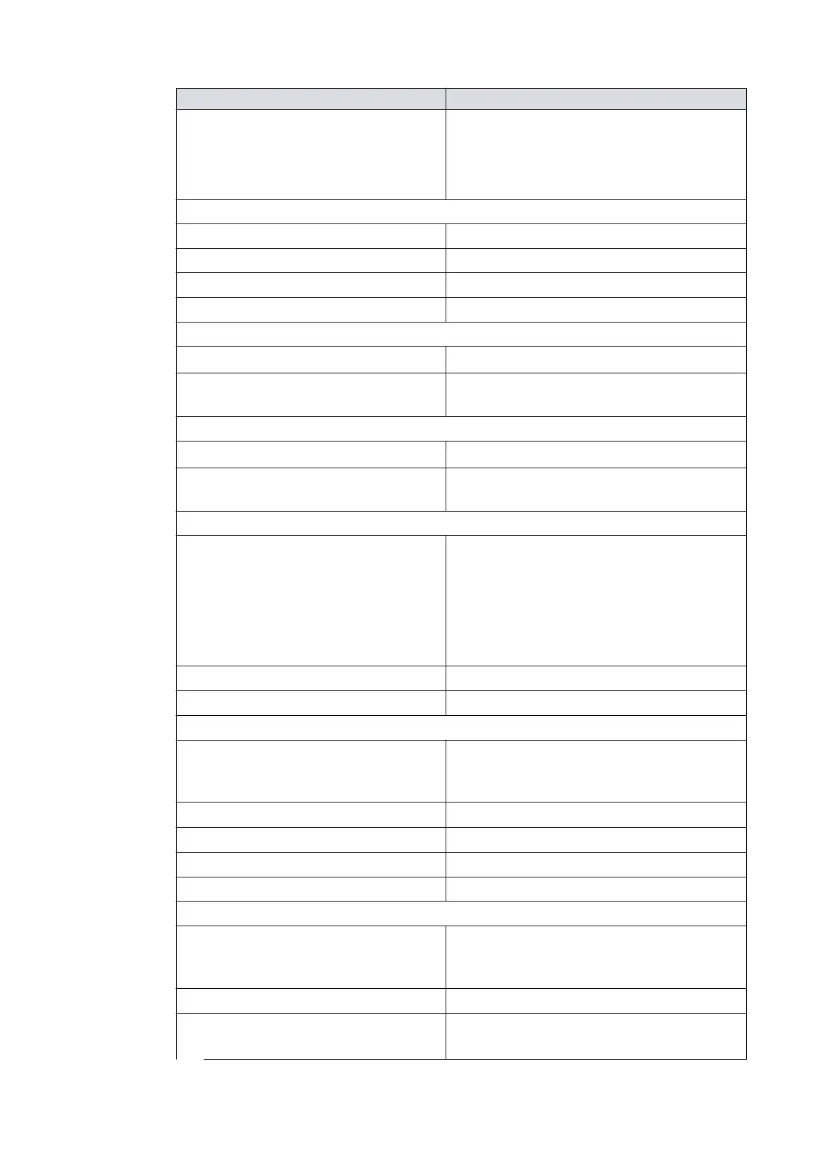
Logic interface item
Fuse rang 10 A f
or 24 V d.c. supply
5 A to 10 A for 48 V d.c. supply
Type 'T' IEC approved or
Time delay fuse UL/CSA approved
Limit of the power supply:
Factory default seng Refer to Pump model descripon on page 12
Maximum seng 200 W
Minimum seng 50 W
Precision of power regulaon ± 10 W
Start and serial enable control inputs:
Enabled control voltage: low (close) 0 to 0.8 V d.c. (I
out
= 0.55 mA nominal)
Disabled control voltage: high
(open)
4 to 26.4 V d.c. (Internal pull up to
6.4 V nominal)
Standby control input
Enabled control voltage: low (close) 0 to 0.8 V d.c. (I
out
= 0.29 mA nominal)
Disabled control voltage: high
(open)
4 to 26.4 V d.c. (Internal pull up to
3.2 V nominal)
Analogue output
Output voltage 0 to 10 V d.c. (directly proporonal t
o the
measured parameter)
Motor speed: 0 ‑ 1000 Hz (0‑100%)
Input power: 0 ‑ 200 W
Motor temperature: 0 ‑ 100 °C
Controller temperature: 0 ‑ 100 °C
Voltage precision ± 0.2 V
Output current
£ 5 mA for specied pr
ecision
Normal status output:
Type
Open collector transistor plus pull up resistor.
Re
fer to Figure: Interface circuits for nEXT tur-
bo pump controllers.
< Normal speed (default 80%)
O (2.2 kW int
ernal pull up to 12 V d.c.)
³ Normal speed
On (< 0.8 V d.c. sinking 20 mA)
Current rang 20 mA t
o 0 V
Voltage rang 28.8 V d.c. maximum external pull up voltage
Fail status output:
Type
Open collector transistor plus pull up resistor.
Refer to Figure: Interface circuits for nEXT tur-
bo pump controllers.
Fail
O (3.3 kW pull up to 12 V d.c.)
OK
On (< 0.1 V d.c. sinking 1.7 mA
,
< 0.8 V d.c. sinking 20 mA)
04/2022 - ©Edwards Limited
Page 32B80000880_G
B80000880_G - Technical data