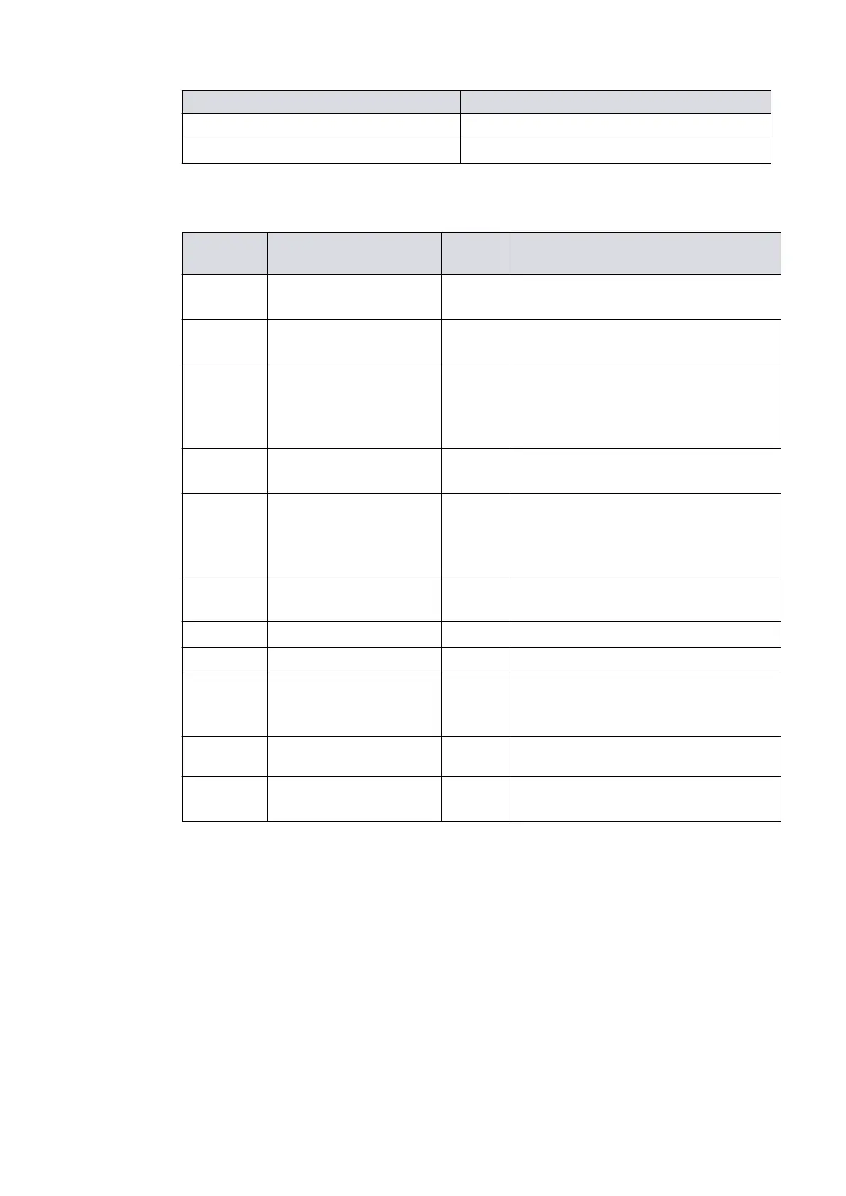
Logic interface item
Current rang 20 mA t
o 0 V
Voltage rang 28.8 V d.c. maximum external pull up voltage
* Mang half of connector not supplied.
Table 11
Logic interface connector pins
Pin Num-
ber
Signal Polarity Use
2 0 V Control reference -
0 V reference for all control and status
signals below.
3
START / STOP control in-
put
- Connect to Pin 2 to start pump
4
STANDBY control in-
put / Serial RX / RS485
A-
-
Connect to Pin 2 to enable standby
speed when serial enable is inacve
and RS485 / RS232 switch is in the
RS232 posion.
5 Serial enable -
Connect to Pin 2 to enable the serial
link
7
FAIL / Serial TX / RS485 B
+
-
Logic high when fail condion exists
and serial enable is inacve and
RS485 / RS232 switch is in the RS232
posion.
9 Analogue output Posive
0 ‑ 10 V output proporonal to meas-
ured output
10 Chassis / Screen ‑ Screen
12 Chassis / Screen - -
15 NORMAL status output -
Logic low when the rot
aonal speed of
the pump is at normal speed or above
the normal speed
8, 13, 14 Electrical supply: 0 V
-
-
1, 6, 11 Electrical supply: 24 V -
48 V d.c.
Posive -
04/2022 - ©Edwards Limited
Page 33B80000880_G
B80000880_G - Technical data