B8J200880_E - Fault finding
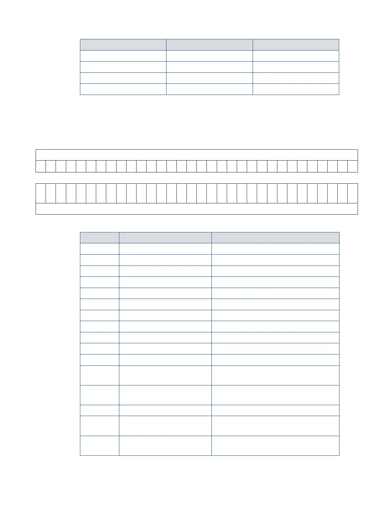
Each binary digit (bit) represents a flag that is either active (state 1) or
not active (state 0). To help decode the System Status Word, each bit is numbered
(starting with 0 for the least significant to 31 for the most significant) as shown below.
contains a list of the lower 16 status flags that will be useful for fault finding. The upper
16 status flags are reserved by us.
V V V V V V V V V V V V V V V V V V V V V V V V V V V V V V V V
Fail status condition active
Above 50% full rotational speed
Exclusive control mode selection
Exclusive control mode selection
Invalid Controller software
Controller internal software mismatch
Controller upload incomplete
Controller failed internal configuration
and calibration operation
Failure to reach or maintain half full speed
within the timer setting value
Overspeed or overcurrent trip activated
Pump internal temperature measurement
system disconnected or damaged
Serial control mode interlock
Serial enable has become inactive
following a serial Start command
The system status word used in the example above was obtained with the pump at rest.
By decoding the word, we can learn more about the state of the pump.