B8J200880_E - Technical data
required. If serial communications is available, the power limit setting of the nEXT pump
can be selected.
Refer to Table: Logic interface technical data for the maximum power limit settings for
nEXT pumps. If the application requires rapid cycling of the pump, faster ramp times can
be achieved if the power supply delivers higher current, up to a maximum in accordance
with Table: Logic interface technical data.
If the facility to adjust the power limit setting is not available, use a power supply
capable of delivering enough current to meet the Edwards factory default power limit
setting, shown in Table: Logic interface technical data.
4.9 Logic interface connector
nEXT pumps have a 15-way logic interface connector on the end of the logic interface
cable. Use a suitable connector mating half (not supplied) to connect the nEXT pump to
the customer equipment. Refer to the following table for the connector mating half
type.
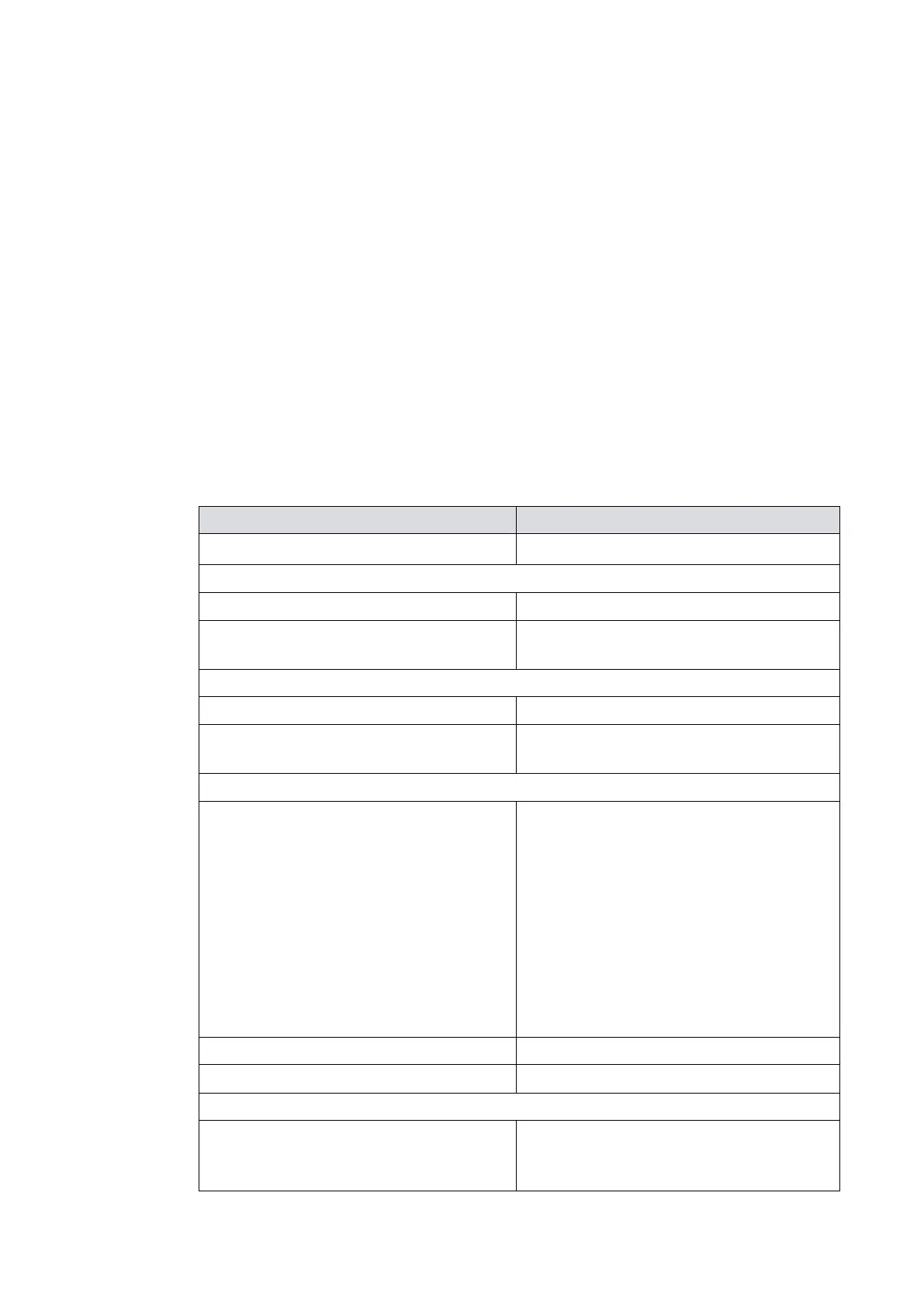
Table 10 Logic interface technical data
Start and serial enable control inputs:
Enabled control voltage: low (close)
0 to 0.8 V d.c. (Iout = 0.55 mA nominal)
Disabled control voltage: high (open)
4 to 26.4 V d.c. (internal pull up to 6.4 V
nominal)
Enabled control voltage: low (close)
0 to 0.8 V d.c. (Iout = 0.29 mA nominal)
Disabled control voltage: high (open)
4 to 26.4 V d.c. (internal pull up to 3.2 V
nominal)
0 to 10 V d.c. (directly proportional to
measured parameter)
Motor speed: 0 ‑ 820 Hz (0‑100%) for
nEXT730/930,
0 ‑ 700 Hz (0‑100%) for nEXT1230
Motor power: 0 ‑ 500 W for nEXT730/930,
0 ‑ 660 W for nEXT1230
Motor temperature: 0 ‑ 100 °C
Controller temperature: 0 ‑ 100 °C
Bearing temperature: 0 ‑ 100 °C
5 mA for specified accuracy
Open collector transistor plus pull up
resistor. Refer to Figure: Interface circuits
for nEXT turbo pump controllers