B8J200880_E - Technical data
< Normal speed (default 80%)
Off (2.2 k pull up to 12 V d.c.)
On (< 0.8 V d.c. sinking 20 mA)
28.8 V d.c. maximum external pull up
voltage
Open collector transistor plus pull up
resistor. Refer to Figure: Interface circuits
for nEXT turbo pump controllers.
Off (3.3 k pull up to 12 V d.c.)
On (< 0.1 V d.c. sinking 1.7 mA,
< 0.8 V d.c. sinking 20 mA)
28.8 V d.c. maximum external pull up
voltage
*
Mating half of connector not supplied.
Refer to the following table for Logic Interface connector pins for the electrical
connections.
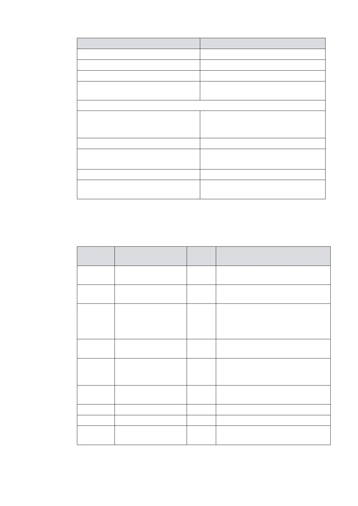
Table 11 Logic interface connector pins
0 V reference for all control and status
signals below.
Connect to Pin 2 to start pump.
STANDBY control input/
Serial RX/RS485 A-
Connect to Pin 2 to enable standby
speed when serial enable is inactive
and RS485/RS232 switch is in the
RS232 position.
Connect to Pin 2 to enable the serial
link.
FAIL / Serial TX/RS485 B
+
Logic high when fail condition exists
and serial enable is inactive and RS485/
RS232 switch is in the RS232 position.
0 ‑ 10 V output proportional to
measured output
Logic low when pump rotational speed
is at normal speed or above