STP-iX455/iXL455 Series Instruction Manual
4-3
Installation
4.1.2 Name and Function of the Control Unit
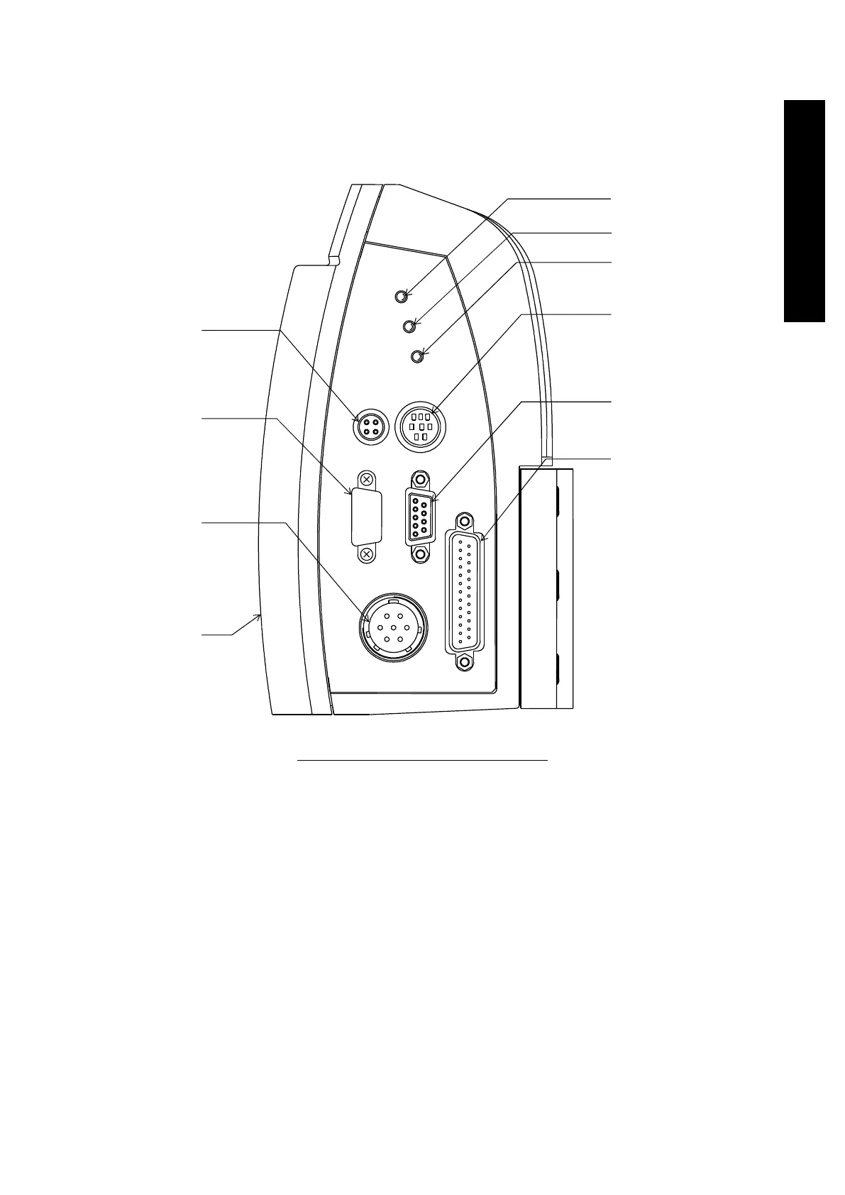
Figure 4.2 shows the front panel and Figure 4.3 shows the rear panel of the control unit.
Figure 4.2 Control Unit (Front panel)
(1) "VENT VALVE" connector (X6)
● For the vent valve (optional accessory) attached in the purge port.
● Refer to Section 4.3.7, "Connecting the Vent Valve" or Section 8.1, "Vent Valve
Output" for details of the connector X6.
(2) "OPTION PORT" connector (X4: COM4) with cover
● For the network unit (optional accessory).
(1)
(2)
(3)
(4)
(5)
(6)
(7)
(8)
(9)
(10)
4
1
2
3
5
6
7
F
A
I
L
U
R
E
R
O
T
A
T
I
O
N
P
O
W
E
R
X
5
S
T
P
-
L
i
n
k
X
6
V
E
N
T
V
A
L
V
E
X
2
R
E
M
O
T
E
X
1
D
C
P
O
W
E
R
X
4
X
3
C
O
M
1