STP-iX455/iXL455 Series Instruction Manual
4-23
Installation
1
2
3
4
5
6
7
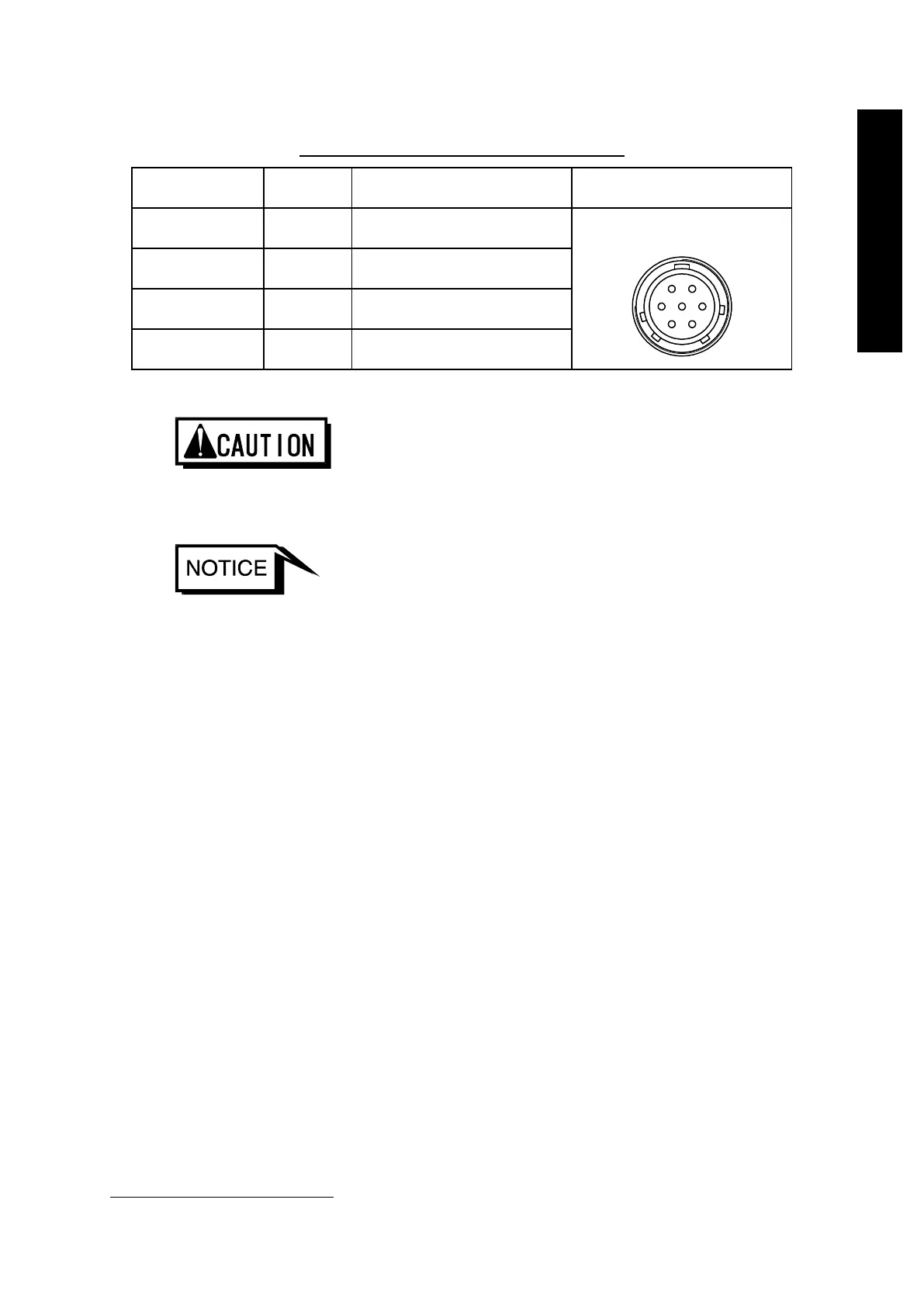
Table 4.6 Pin Assignment for Connector X1
pin No
Signal Remarks Outline
1 +48 V For +48 VDC power supply
2 0 VA
power supply
3, 4, 5, 6 –
pins
*1
7 FG Frame ground
◇ Connect the external power supply unit to No.1 and No.2 pins of the connector X1.
Failure to do so may result in product damage.
◇ Refer to the iPS-240 Instruction Manual for the operation of the power supply unit
(optional accessory).
◇ No. 2 pin (0VA) and No. 7 pin (FG) of the connector X1 are connected internally to
the pump body and other metallic components.
◇ The STP pump mounts 7 A fuse in DC power supply input line as overcurrent
protection.
*1
: It is equipped for a power supply unit iPS-240 (optional accessory).