21
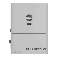
Steps for PV Wiring:
1. Ens
ure all breakers and disconnect switches
are in the OFF position before connecting or
disconnecting wires. Use a voltmeter to
confirm there is no voltage present.
2. Strip off 1/4 in. – 5/16 in. (6 mm – 8 mm)
insulation on the PV string’s positive and
negative conductors.
Note: Use wire ferrules for the PV string
conductors if they are stranded wire.
3. Insert the conduit fitting into the opening for
the PV connection and tighten it from the
inside using the counter nut.
4. Route the PV conductors through the conduit fitting and into the inverter.
5. Secure the PV conductors in place into the inverter inputs by inserting a flathead screwdriver into
the square and the conductor into the circular input. Verify that they are secured properly by
lightly pulling on them.
6. Ensure the conduit and conduit fittings are fastened securely and the cable entry holes are
sealed.
7.5 CONNECTING BATTERIES TO THE INVERTER
The FlexBOSS21 comes equipped with two battery positive terminals and two battery negative
terminals. Each of the two positive battery terminals are protected by a 300 amp breaker. This is to
accommodate using parallel conductors as supplied with the WallMount battery series. It is designed
to utilize 4/0 battery cables up to 20 feet by using two sets of cables rather than resorting to larger
cable sized.
Cable Requirements
2
Max. 22.9 ft-lbs. (31.1Nm)
2
Max. 22.9 ft-lbs. (31.1Nm)
2 Sets 1/0 AWG (53.5 mm
2
) 10 ft. Max. 165 in-lbs. (18.6Nm)
2 Sets 2/0 AWG (67.4 mm
2
) 20 ft. Max. 165 in-lbs. (18.6Nm)
IMPORTANT!
According to the NEC (National Electric Code) in the USA, all PV systems above 50V
must have one current-carrying conductor connected to the ground/earth.
All exposed metal parts of the system must be grounded, regardless of