25
Steps for AC Connection:
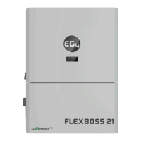
The FlexBOSS21 comes equipped with a L1 and L2 terminal for AC input (labeled GRID) and output
(labeled LOAD). It is designed to utilize up to 50A of input and up to 66.7A of output. These terminals
ARE NOT connected to a breaker; check with the local AHJ for requirements for means of
disconnect.
1. Before connecting or disconnecting
AC wires, ensure all breakers are in
the OFF position. Check that there
is no voltage present with a
voltmeter.
2. Strip off 5/16 – 3/8 in. (8 – 10 mm)
insulation from the AC cables.
Note: Use wire ferrules if the cables
are made of fine stranded wires.
3. Connect the AC ground wire to the
ground bus (labeled PE).
4. Fasten the neutral wire into the
neutral bus (Labeled N).
5. Secure the AC wires into their respective mechanical lugs (Line 1 to L1, Line 2 to L2). Torque to
the specifications in the chart above.
6. Check that the cables are connected properly. Take appropriate measures to ensure that the
conduit and conduit fitting are properly secured and seal the cable entry holes.
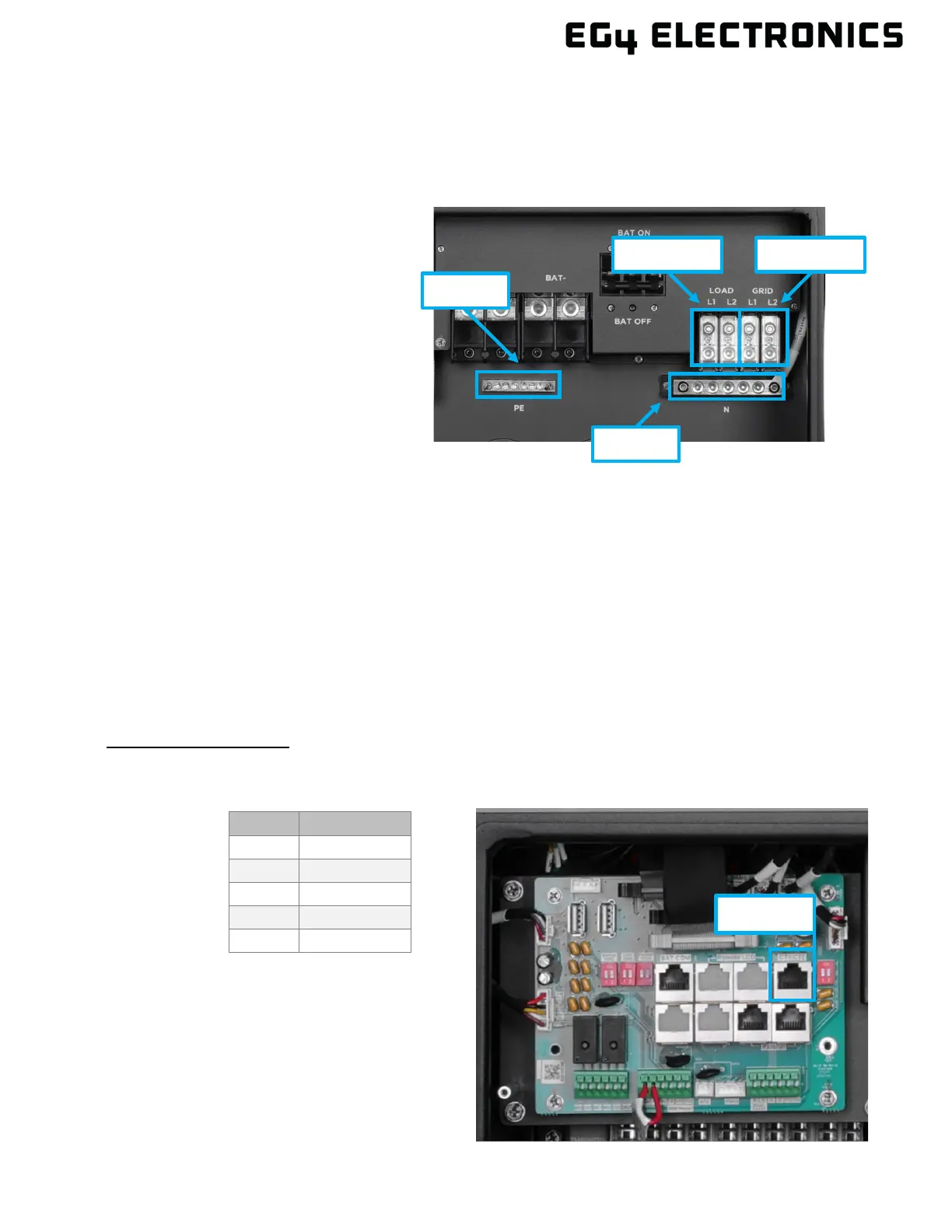
CT/Meter Connection
To measure the power imported from and exported to the grid, a pair of CTs or one three-phase
meter must be installed at the service entry point in or near the main service panel. Two CTs are
provided with each inverter. The inverter is capable of a third-party meter connection; see section
10.6 for more information.
CT P
ort Pin Definition:
The CT interface for the two (2) CT connections is an RJ45 port. The two (2) CTs come with
premade plugs that can be connected directly to the port.
Pin Description
1 – 4 Reserved
5 CT2N
6 CT2P