26
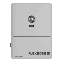
Refer to the connection diagram to the
right for the correct position of the CTs.
Clamp the 2 CTs onto the L1 and L2 wires
at the service entry point in the main
service panel as close to the meter base
as possible.
The arrows on the CTs must point
toward the inverter and be placed on
the proper line based on their number.
(CT 1 for L1, CT 2 for L2)
CT Clamp Ratio:
The inverter supports three ratios of CT clamps:
1000:1, 2000:1, and 3000:1. The included CTs
are 3000:1.
If using a 3
rd
party CT, ensure that the CT ratio is
of the supported types. Be sure to select the
correct CT ratio setting on the inverter.
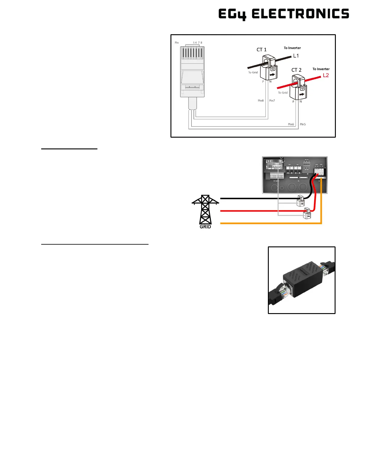
Black= L1
Red= L2
Orange= Neutral
Grey= Communication Cable
Extending the CT Clamp Cable:
The CT wires can be extended with a common ethernet cable if they are
not long enough. An RJ45 adapter is needed for the extension. The CT
wires can be extended up to 300 ft. (around 90 m).