Mounting, installation and connection Operating manual - Fan CF-C
46 of 84 www.elektror.com 2004930 10.19/0.2
EN
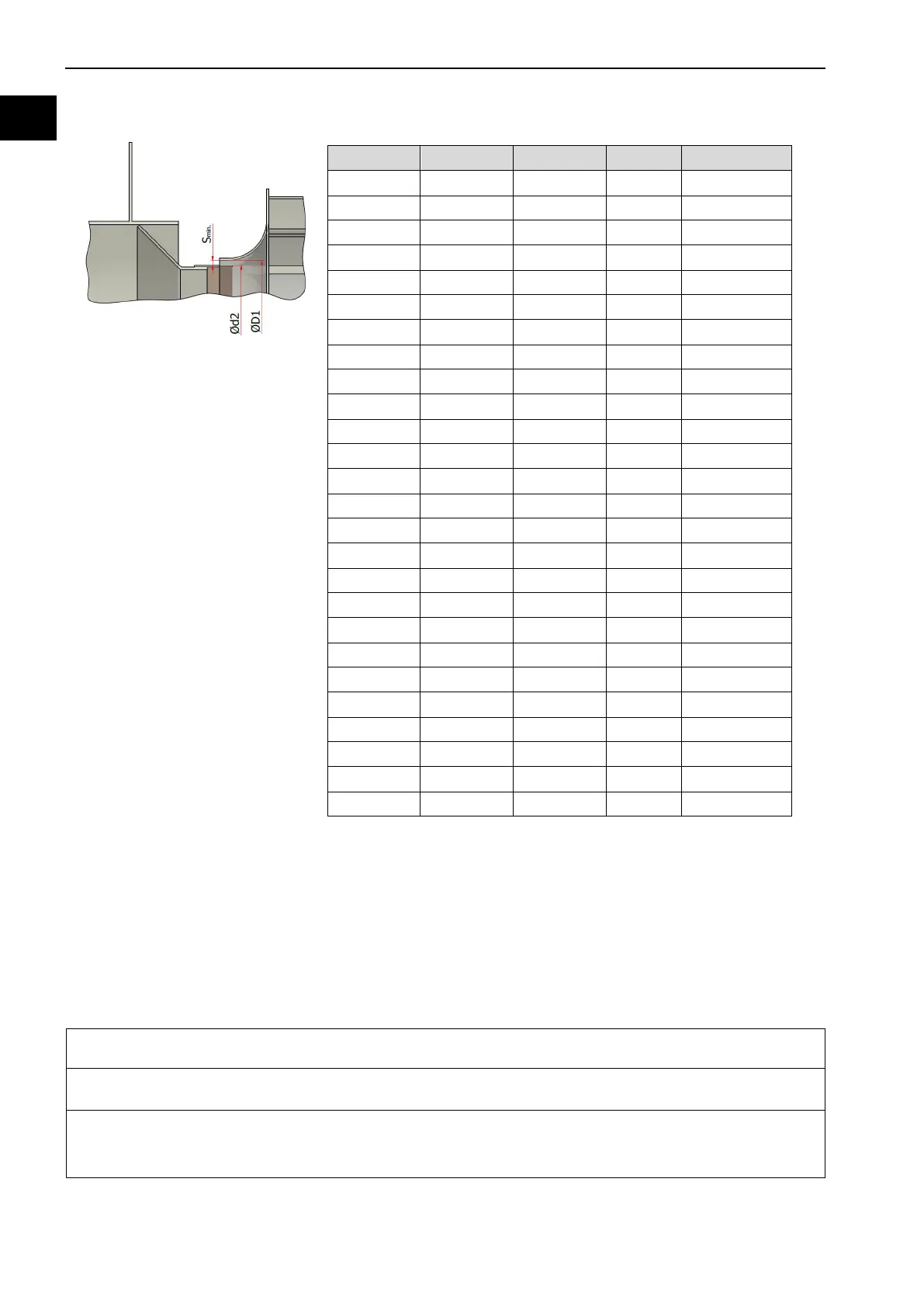
6.7.2.3 Impeller with cone
Situation of impeller installed with
cone
Table 10: Minimum gap width – impeller with cone (ATEX)
112 112 90 76
125 125 100 84
140 140 112 102
160 160 126 116
180 180 141 130
200 200 158 148
224 224 178 168
250 250 199 188
280 280 224 212
315 315 251 240
355 355 282 270
400 400 316 304
450 450 355 342
500 500 398 384
560 560 447 432
630 630 501 484
710 710 562 542
800 800 631 612
900 900 708 688
1000 1000 794 770
1120 1120 891 866
1250 1250 1000 970
1400 1400 1120 1090
1600 1600 1280 1250
1800 1800 1390 1350
2000 2000 1600 1560
6.7.3 Installation of compensators
The compensators need to be installed only after the pipeline has been assembled.
Hose compensators
The hose compensators are pulled on the pipeline and fixed with hose clamps.
1. The hose compensator should be carefully pushed onto the pipeline.
2. The hose compensator should then be secured with hose clamps.
Result:
The hose compensator is installed.