74
Pos: 7.1 / 00 20 Ü bers chr ift en/E LTR A 1. Üb ers chri fte n/1 Adj ust me nts, t ests a nd worki ng i nst ruc tio ns E LTR A @ 6\mod_1368775845833_9.docx @ 41360 @ 1 @ 1
4 3BAdjustments, tests and working instructions
Pos: 7.2 / 00 20 Ü bers chr ift en/E LTR A 1.1 Ü bers chr ift en/ 11 G as fl o w co ntrol ler adj ust men t an d j ump er s etti ngs ELTR A @ 6\mod_1368776355883_9.docx @ 41371 @ 233332 @ 1
4.1 43BGas flow controller adjustment and jumper settings
Pos: 7.3 / 00 10 ELTR A/0 015 s er vice _i nstr ucti ons /CS- 800_ Ser vic e/0 020 Ein stel lu ngen , Tes ts un d Fu nkti ons besc hr eibu ng/0 205 Mo dul Gas fl ow c ontr oll er adjus tm ent and j u mper s et ting s @ 6\mod_1377688625026_9.docx @ 46855 @ 31 @ 1
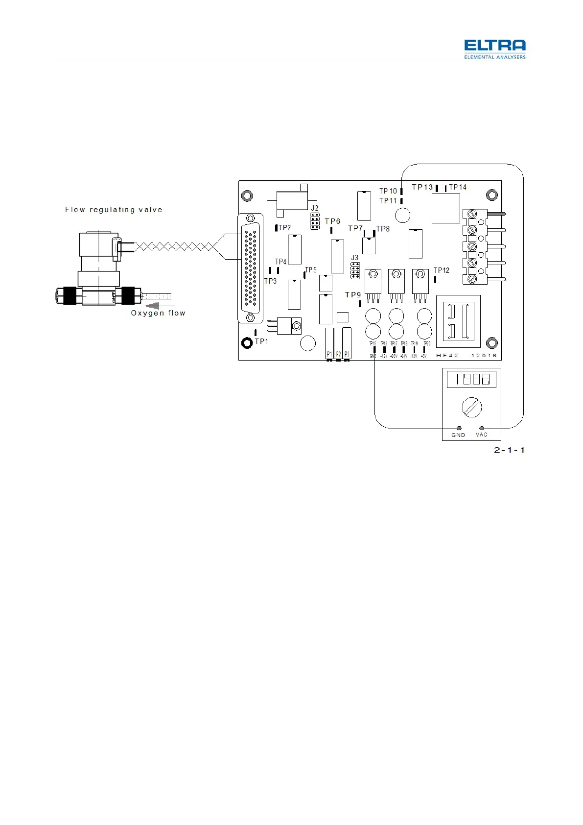
Abb. 43: Gas flow controller
• Set the flow rate with P1 of the HF 42, to about 180 l/h. Observe the flow
rate on the lower flow meter of the analyzer. Wait until the value is stable.
The output of the flow sensor is found on TP10 of the HF 42 board; TP15 is GND.
With a flow of 180 l/h, the voltage is about 2.5 - 3V.
Please note: without flow, the output voltage of the
sensor is not 0V but about 0.6V.
• Adjust with P3 until the voltage on TP7 is 5V.
On TP8, the activity of the pulse width modulator can be checked.
The output voltage to the gas flow regulation valve can be measured on TP3.
With a constant flow of about 180 l/h, it should be between 5 and 15 volts.
• Check and if necessary readjust the pressure regulator (PR3) in front of the
flow regulating valve.