78
The HF 42 board drives the flow regulating valve (V6) in such way, to provide a
constant and accurate gas flow.
Remark:
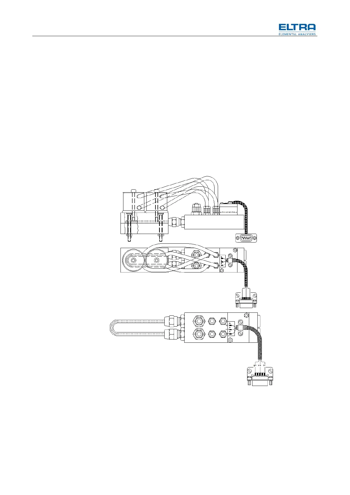
Due to a few failures of the flow sensors, almost exclusively on the CS-800 at
customers who regularly treat their samples with acid, we concluded that the
reason of the failures should be of chemical nature i.e. acids and Schutze`s
Reagent damage the sensor.
The solution is to prevent the analysis gases to get in contact with the sensors.
Therefore the sensor ports are connected with long tubes to the gas flow system.
There is no gas flow through the sensor tubes but only the pressure is sensed by
the sensor.
In case of failure of a previous version sensor, it is advisable to replace it by the
new version. In this case the part numbers of the complete assemblies should be
used for ordering. In case the analyzer has already the new version sensor, the
order should include the spare part number. See attached drawings.
The new flow sensor cannot be used as a replacement for the older flow sensor
consisting of a rotameter and a optical element.
Fig. 28: Flow sensor
Pos: 7.8 / 00 20 Ü bers chr ift en/E LTR A 1.1 Ü bers chr ift en/ 11 I nfr ared bas e li ne adj ustm ents E LTRA @ 6\mod_1369121936836_9.docx @ 41542 @ 2232 @ 1
4.2 44BInfrared base line adjustments
Pos: 7. 9 /002 0 Übersc hrift en/ELT RA 1. 1.1. Üb erschri fte n/111 In frare d cell modi fica tion - ge ner al i nf ormati on ELT R A @ 6 \mod_1369220851611_9.docx @ 41800 @ 43234 @ 1
4.2.1 104BInfrared cell modification - general information