36
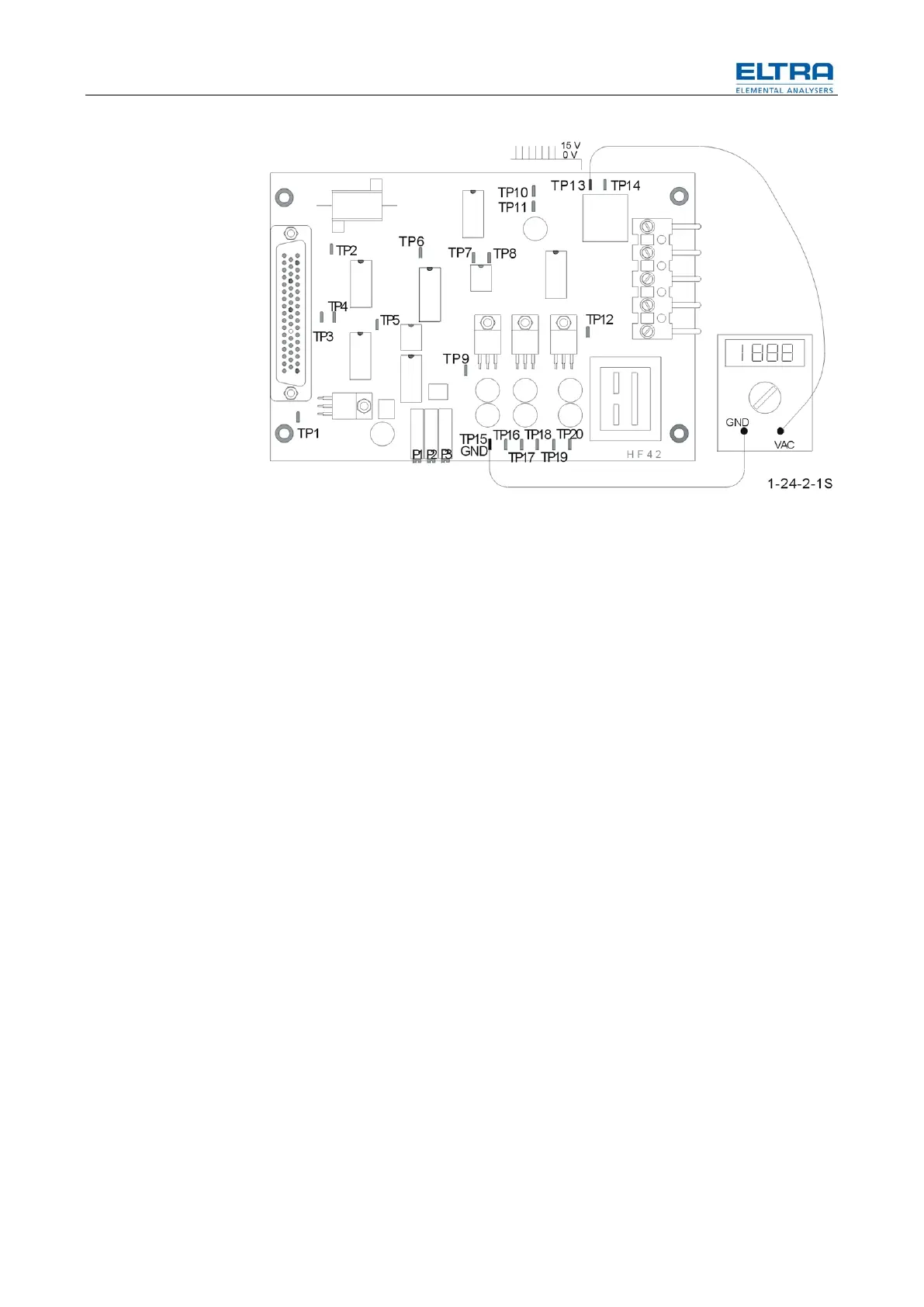
Fig. 14: TP13 test point
When the command for the generator is received ( 0.5 V DC ), the triac triggering
pulses must appear on the TP13 test point. If there is no oscilloscope available you
can test this with a digital voltmeter. The displayed value depends on what type of
digital voltmeter you have. There must be a voltage increase on TP13, once the
word "Analyzing" has appeared on the display, or once 0.5 V are present on TP9.
When no voltage increase occurs on TP13, despite having 0.5 V on TP9; the HF
42 circuit board is defective.
NOTICE
After replacing the HF 42 board, make sure that the 50 pin plug is properly
inserted. It takes a lot of force to push in 50 pins at once. 50 pin plugs that haven’t
been properly inserted are a frequent problem. Tighten the screws of the plug
properly, to ensure a proper connection to the board.
3.4.7.2 Checking the generator tube
Ensure that the power switch is at position 2.
Check if the filament of the generator tube glows:
This can be easily checked:
Through the air vent holes of the furnace, the reflected light of the glowing
filaments (heater of the cathode) should be visible.