Service
114
• Remove the tubes (10) and (11) at the bottom-side of the infrared rack
• Unplug the plug (1)
• Pull out the infrared rack from the analyzer
• Remove the left side cover (2), the top cover (3) and the bottom cover (4)
of the infrared rack
• Remove the two tubes (5) and (6) from the flow sensor (9)
• Remove the two screws (7) underneath the flow sensor.
• Remove the old flow meter, install the new one.
• Reassemble the infrared rack in reverse order.
– Pay particular attention to the position of the tubes (5), (6), (10) and (11).
• Adjust the flow sensor.
Pos: 9.20 /0 020 Über sc hrif ten /ELT RA 1.1 Über sc hri ften /11 F ur nac e pn eum atic s - ad diti onal s afet y f eatur es ( opti on al) ELTR A @ 6\ mod_1369643455549_9.docx @ 42531 @ 222222232 @ 1
5.10 61BFurnace pneumatics - additional safety features (optional)
Pos: 9.21 /0 010 ELTR A/ 0015 s ervic e_i nstr uc tio ns/C S-800 _S ervic e/ 002 5 Ser vic e/ 038 0 M odul F ur nac e pn eum atic s - additi on al s afet y fe at ures (o ption al) @ 6 \mod_1377688644179_9.docx @ 47263 @ 323243344 @ 1
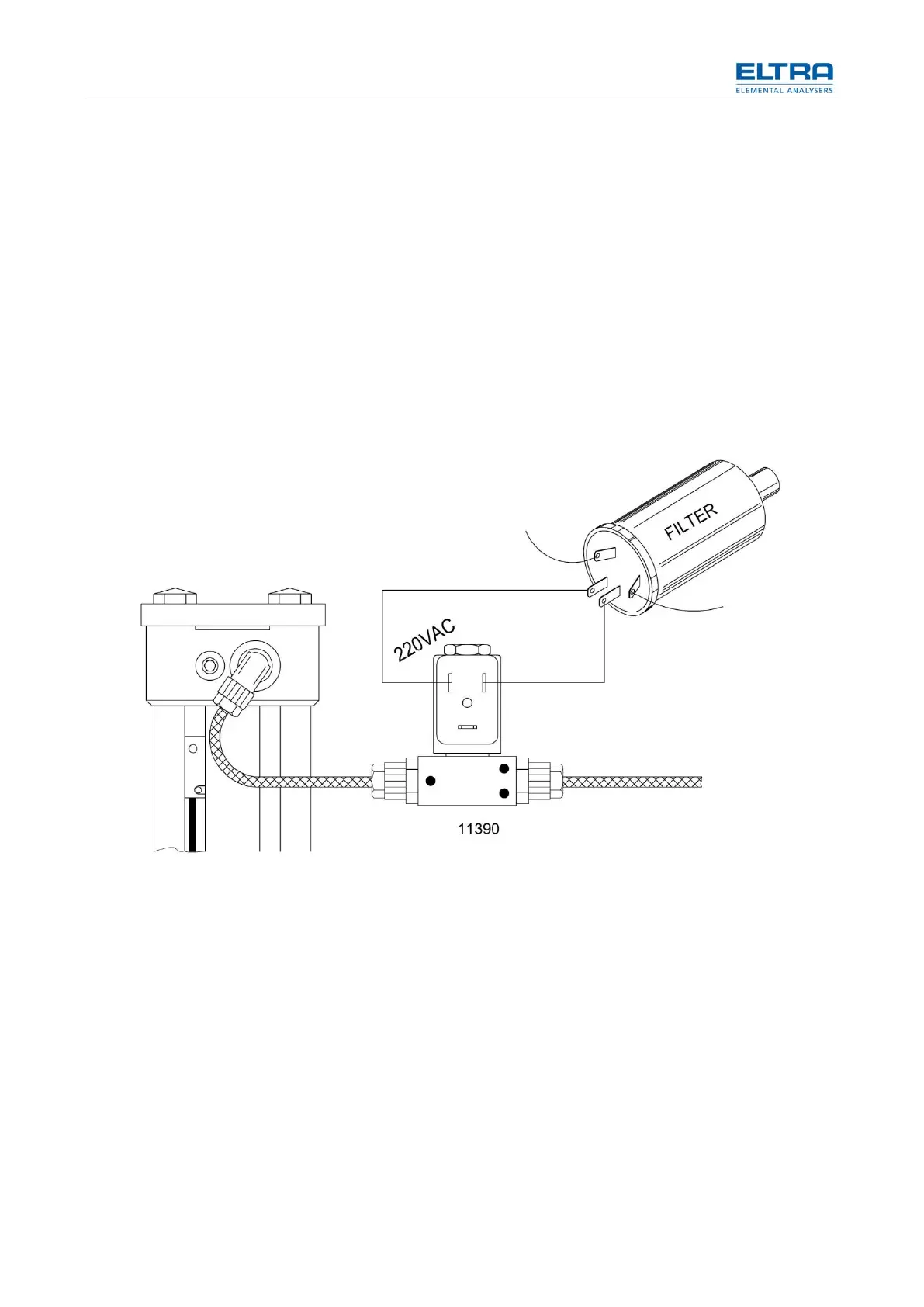
The furnace doesn’t change position in case of a power failure.
Fig. 62: Furnace power failure
By adding a solenoid valve (8) and connecting the coil directly to 220V AC, the
piston won’t change position in case of a power failure. If the piston was down, it
will remain down; if it was up, it will remain up.

 Loading...


