84
TP 23: Output section [4]
Pos: 7.11 /00 20 Ü ber sc hrift en/ ELTR A 1 .1. 1. Ü bers chr ift en/1 11 Bas e li ne a dju st ment s ELT RA @ 6 \mod_1369220944651_9.docx @ 41811 @ 3333 @ 1
4.2.4 107BBase line adjustments
Pos: 7.12 /0 010 ELTR A/ 0015 s ervic e_i nstr uc tio ns/C S-800 _Ser vice/ 0020 Ei nstell ung en, Te sts und Fun kti ons bes chr eibu ng/ 023 0 Mo dul Bas e li ne adj ustm ent @ 6 \mod_1377688627211_9.docx @ 46915 @ 32344344 @ 1
When the IR module (rack) is removed from the analyzer, it can be powered on the
desk by a 24VDC power supply connected to J1 of the IRC board. The power
supply should normally be capable to supply a current of 5A.
If a lower current power supply available, in order to prevent the temperature
control from taking high current from the power supply, set a jumper to position 2 of
the connector J1. In this case a 24V / 1A power supply will be enough.
NOTICE
Remember to remove the jumper from position 2 before reinstalling the IR module
into the analyzer, otherwise the thermostatic control will not work.
Pos: 7.13 /0 020 Über sc hrif ten /ELT RA 1.1 .1. Ü ber sc hrift en /11 1 Infr ar ed c ell bo ard I RC1 .x s ect ions ass ign men t ELT R A @ 6\mod_1369220999064_9.docx @ 41822 @ 3324343 @ 1
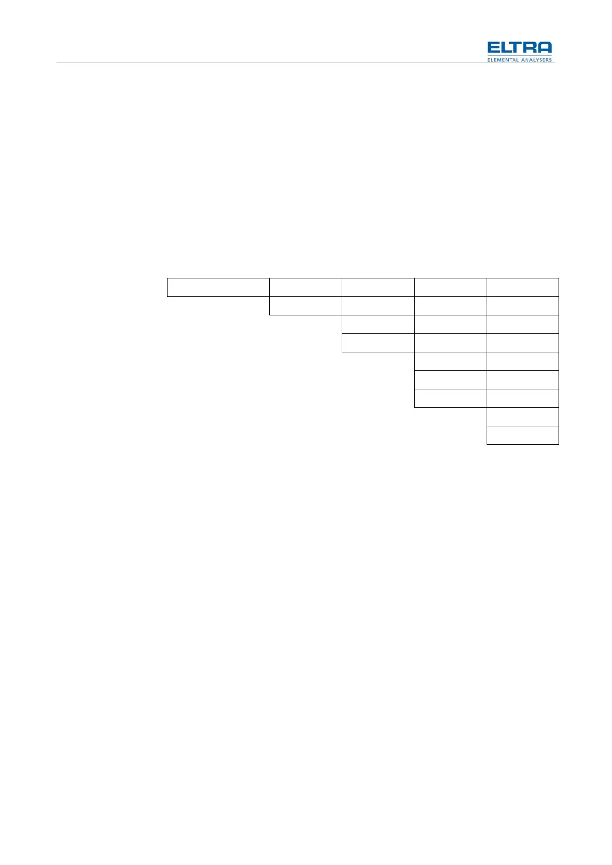
4.2.5 108BInfrared cell board IRC1.x sections assignment
Pos: 7. 14 /0 010 ELTR A/ 0015 s ervic e_i nstr uc tio ns/C S-800 _S ervic e/ 002 0 Ei nst ell unge n, T ests u nd F unk tio nsbe schr eib ung /0 235 M odul IR c ell t emp reg ulat ion gen er al d escri pti on @ 6\ mod_1377688627445_9.docx @ 46927 @ 4244444434344343444 @ 1
board sections [4] [3] [2] [1]
4 cells IR module Hi S Lo S Hi C Lo C
3 cells IR module S Hi C Lo C
3 cells IR module Hi S Lo S C
2 cells IR module S C
2 cells IR module C C
2 cells IR module S S
1 cell IR module C
1 cell IR module S
4.2.5.1 Explanations
– Lo C: Low carbon range (long C path)
– Hi C: High carbon range (short C path)
– Lo S: Low sulfur range (long S path)
– Hi S: High sulfur range (short S path)
– C: single carbon range (single C path)
– S: single sulfur range (single S path)
The preamplifier connectors of the cells are of course connected to the
corresponding sections according to the above assignment list.
(4-pin module connectors).
4.2.5.2 Example
A three cell module with a low carbon, a high carbon and a sulfur cell has
– the low carbon signal on section [1], the LoC preamp is on X1
– the high carbon signal on section [2], the HiC preamp is on X2
– the Sulfur cell signal on section [3], the S preamp is on X3
The base line adjustments are done by adjusting the gain of the preamplifier of
each IR cell in the IR module (rack). The gain adjustment is done by turning the
trimmer which is inside of each preamplifier. The base line voltages can be
measured on the following test points:
Outputs (base lines about 8VDC)
TP 22: Output section [1]
TP 25: Output section [2]