77
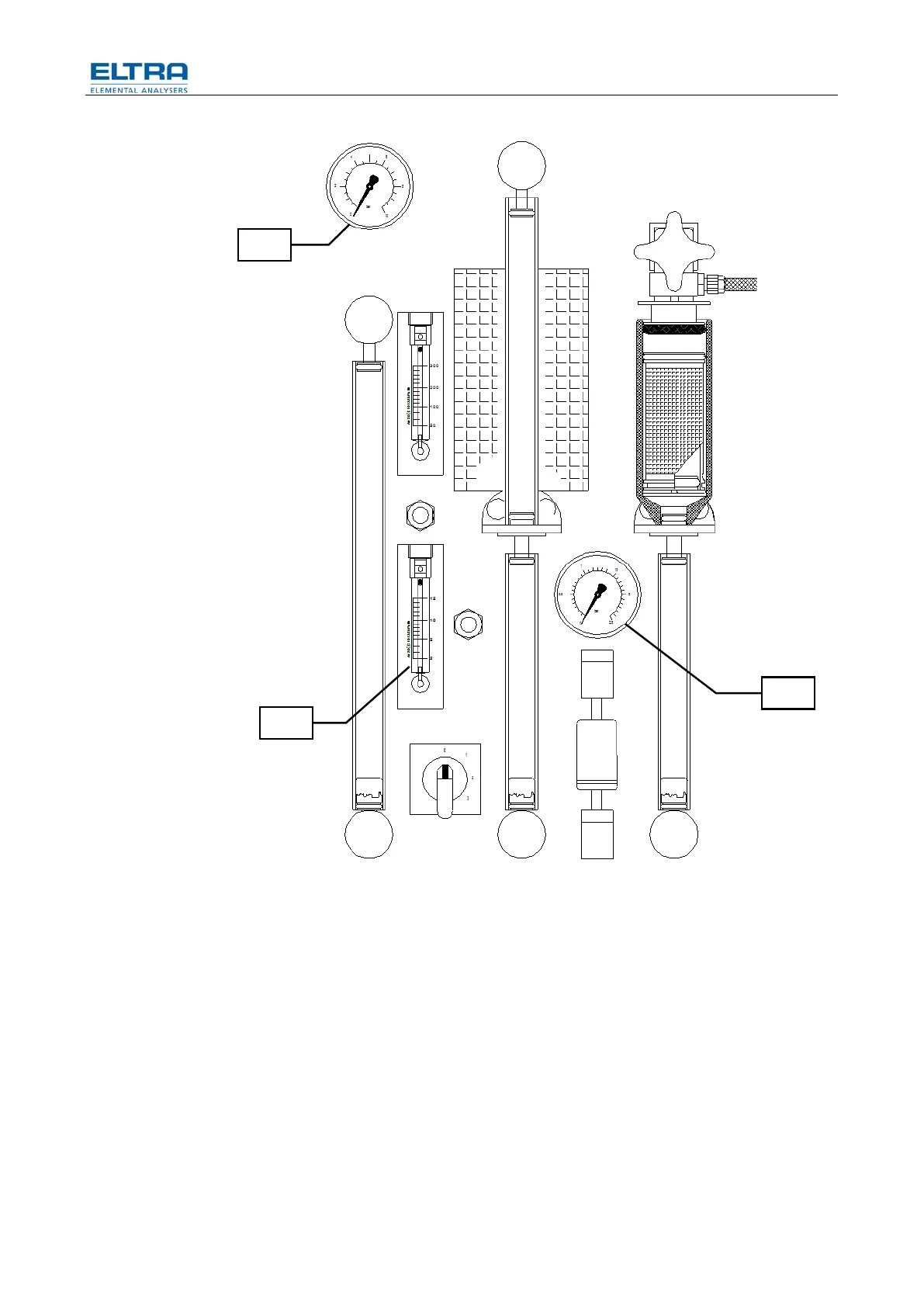
Abb. 45: Front panel
The flow controller mainly consists of the following components:
– The flow sensor (1)
– The flow regulating valve (V6)
– The flow control board HF 42
The flow sensor measures the gas flow, and converts its flow rate into an electrical
signal (DC voltage).
The HF 42 board compares this flow value with the flow set point value.
The signal resulting from the comparator controls a pulse width modulator.
Its output can be seen on TP 8. TP 15 is GND.
The pulse width modulated signal runs a power transistor, which in turn, supplies
the output signal to the flow regulating valve.
The duty cycle of the output signal determines its DC voltage, which, with a flow of
about 180 l/h and with clean chemicals, measures around 9V (on TP 3).
5
6
7