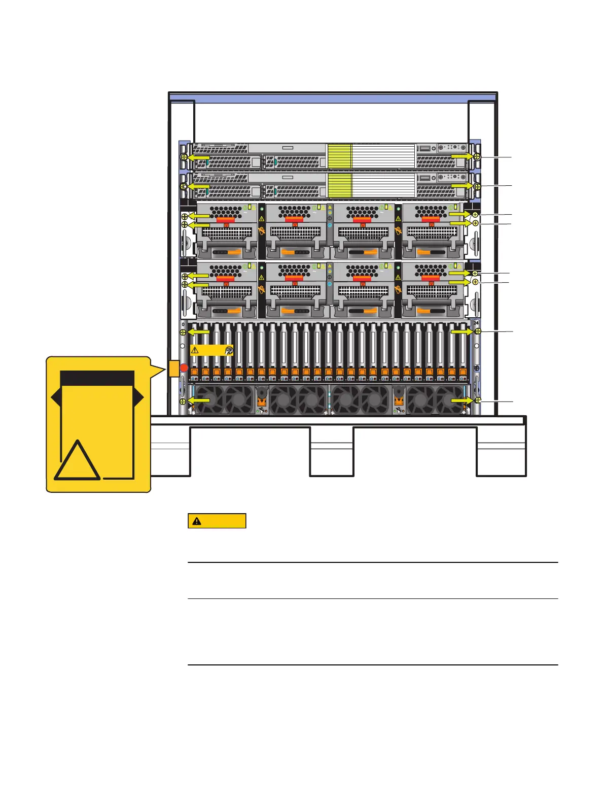
Figure 1 Mini-rack components
AC
AC
AC
AC
PS A0
PS A1
CPU A
A
B
PS B0
PS B1
CPU B
Front
Disk-processor enclosure (Jetfire)
A
B
SP
SP
Will Make the Array Unusable
Caution: Array Software on drives 0-3. Removing or relocating them
01
01
2
3
4
8
AC
AC
AC
AC
A
B
PS B0
PS B1
CPU B
5
6
PS A0
PS A1
CPU A
WARNING!
USE CAUTION
during installation
and removal of
connector through
NEMA rail
!
Some of the components in the mini-rack are heavy and might require two people. If
needed, use an appropriate lifting device (mechanical lift).
4. Starting from the top of the mini-rack, carefully slide the Control Stations (CS0 and
optional CS1) out of the mini-rack.
When you slide out the CSs, there are slide rails (inner slide rails) attached to each
Control Station. Do not take these rails off. These rails will be used later when
installing the Control Stations in the site rack.
a. Pull the Control Station forward until it locks into place as shown in Figure 2 on
page 17.
Unpack your system
16 EMC VNX Series VNX5600 Unified Installation Guide

 Loading...


