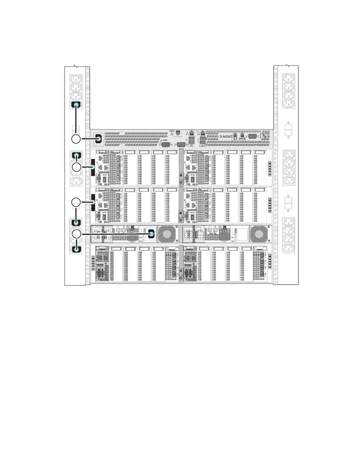
Figure 41 Connecting the black power cables for PDU B
2. From blade enclosure 0 (B side) to PDU B. See cable 2.
3. From blade enclosure 1 (B side) to PDU B. See cable 3.
4. From CS0 to PDU B. See cable 4.
5. Wait 15 minutes for the system to power up completely.
6. If the optional CS1 is installed as shown in Figure 42 on page 57 wait until step 5 on
page 56 completes and the SP Fault LED is turned off, then connect CS1 to PDU A.
Power up
56 EMC VNX Series VNX5600 Unified Installation Guide

 Loading...


