February 2019
User Instructions
MAN-02-04-60-0350-EN Rev. 3
17
Section 4: Installation Instructions
Installation Instructions
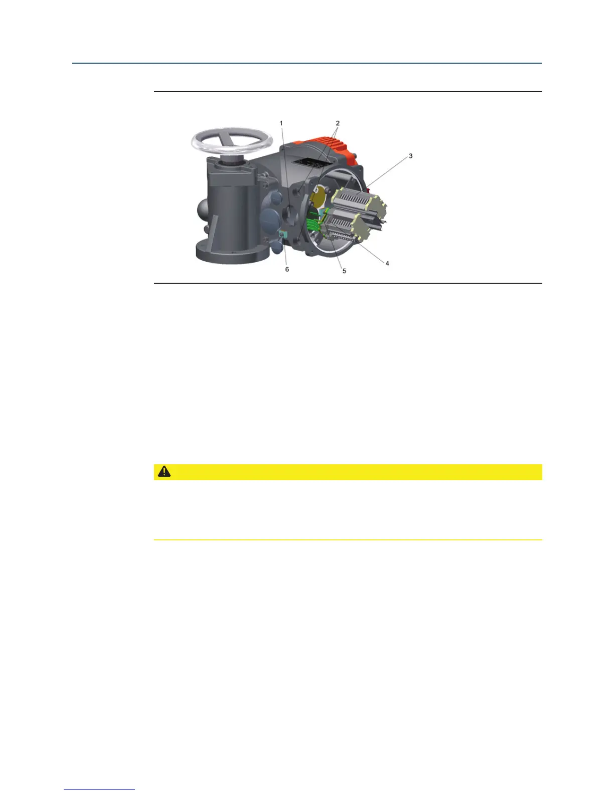
Figure 10 Bettis RTS Terminal Box
Terminal Box Overview:
1. Metric screw M40x1,5
2. 2 x M20x1,5
3. M25x1,5
4. Terminals for the power supply
5. Terminal for ground connection
6. Outside ground connection
Explosion-proof actuators or on special request the connection will be mady via terminals
(see Figure 10).
CAUTION: OBSERVE CORRECT PROCEDURE
If, during outdoor installation, commissioning is not carried out immediately after
electrical connection, the power supply must be connected at a minimum to achieve a
heating effect. In this case, the silica gel may remain in the connection compartment until
commissioning. (see Section 3.3)
 Loading...


