Liquiline System CA80SI Commissioning
Endress+Hauser 49
10.1.3 Connecting sample inlet hose "SPx"
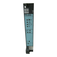
A0036036
1 Sample outlet hose "D" and either sample inlet hose SP1 and SP2 (1-/2-channel version) or SPx (4-/6-channel
version)
2 Outlet hose "W"
3 4-/6-channel version: Cable connection for panel
4 Connections for sensors, signal lines
5 Power cable
1-channel version
A constant and sufficient supply of sample must be ensured at the installation
location.
1. Remove the drain plug from sample channel 1. Do not remove the drain plug in
sample channel 2. Ensure that the needle valve of sample channel 2 is always closed.
2. Connect sample inlet hose SP1 to sample channel 1 and guide it out of the housing
via a hose gland.
3. Secure sample inlet hose SP1 with a PG gland with the appropriate clamping unit.
4. Connect sample inlet hose SP1 to the pressure relief valve. Keep the length of hose
between sample inlet hose SP1 and the pressure relief valve as short as possible.
2-channel version
A constant and sufficient supply of sample must be ensured at the installation
location.
If a sample channel is not in use, do not remove the red drain plug in the valve.
1. Remove the drain plug from the sample channels.
2. Connect sample inlet hoses SP1 and SP2 to the sample channels and guide them out
of the housing via a hose gland.
3. Secure sample inlet hoses SP1 and SP2 with a PG gland with the appropriate
clamping unit.
4. Connect sample inlet hoses SP1 and SP2 to the pressure relief valves. Keep the length
of hose between the sample inlet hose and the pressure relief valve as short as
possible: max. 0.5 m (1.64 ft).
4-/6-channel version
A constant and sufficient supply of sample must be ensured at the installation
location.
If a sample channel is not in use, leave the red drain plug in the valve.
1. Remove the drain plug from the sample channels.
2. Using the SPx sample inlet hoses, connect the channels of the panel with the sample
channel switching to the pressure relief valves of the panel. Keep the length of hose
between the pressure relief valves and the panel with the sample channel switching
as short as possible: max. 1 m (3.28 ft).

 Loading...