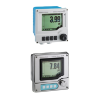
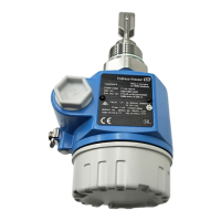
Operation Liquiline System CA80SI
88 Endress+Hauser
You can define a maximum of 16 analog device variables (AI).
1. Define the data source.
You can choose from the analyzer as well as sensor inputs and controllers.
2. Select the measured value to be output.
3. Define how the device should behave in the hold state (for sensors). (Configuration
options of Source of data, Measured value and Hold behavior) → 81
4. In the case of controllers, also specify the type of manipulated variable.
Please note that if you select Hold behavior = Freeze , the system not only flags the status
but also actually "freezes" the measured value.
In addition you can define 8 digital device variables (DI):
‣
Define the data source.
You can choose from relays, binary inputs and limit switches.
For further information on "EtherNet/IP", see the Guideline for Communication via
EtherNet/IP, SD01293C
11.6 Additional functions
11.6.1 Limit contactors
There are different ways to configure a limit switch:
• Assigning a switch-on and switch-off point
• Assigning a switch-on and switch-off delay for a relay
• Setting an alarm threshold and also outputting an error message
• Starting a cleaning function (for sensors)
Menu/Setup/Additional functions/Limit switches/Limit switch 1 ... 8
Function Options Info
Source of data Selection
• None
• Sensor inputs
• Binary inputs
• Controller
• Fieldbus signals
• Mathematical functions
• MRS set 1 ... 2
Factory setting
None
‣
Specify the input or output which is to be the
data source for the limit switch.
The sources of data on offer depend on your
device version.
You can choose from connected sensors, binary
inputs, fieldbus signals, mathematical functions,
controllers and sets for measuring range
switching.
Measuring value Selection
Depends on:
Source of data
‣
Select the measured value, see the following
table.
Measured value depending on the Source of data
Source of data Measured value
Selection
Main value
pH Glass Selection
• Raw value mV
• pH
• Temperature
pH ISFET
 Loading...
