Note:
• The contact position on mains
failure or when a fault occurs can
be set for “contact 1" and ”alarm
contact” through the system
configuration.
Note
• All switching contacts are
interference-suppressed.
External loads must also be
interference-suppressed.
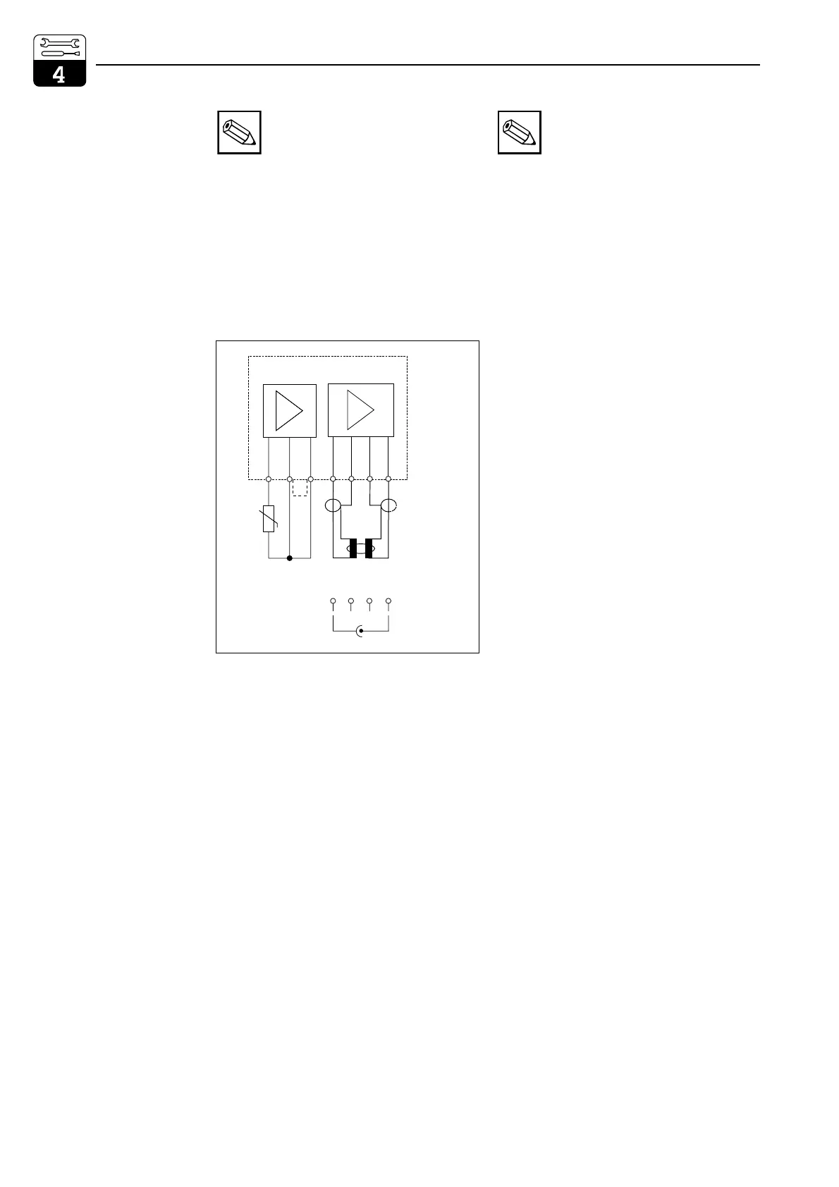
FCL1 additional module:
For second conductivity input.
11 Pt 100 terminal, sensor line
12 Pt 100 terminal, sensor line
13 Cable compensation terminal
For inductive sensor
14 Transmitter coil inner conductor
15 Transmitter coil screen
16 Receiver coil screen
17 Receiver coil inner conductor
For conductive sensor
14 Electrode cable screen
15 not connected
16 not connected
17 Electrode cable inner conductor
Measuring channel allocation
Cond.1 / temperature 1 Slot 1
Cond.2 / temperature 2 Slot 2
11 12 13 14 15 16 17
Pt 100
fcl1.cdr
inductive
conductive
Only
two-electrode
sensors
connectable
14 15 16 17
n.c. n.c.
send (wt)
receive (rd)
bl rd rd bl
Fig. 4.8
Connection of
FCL1 module
Installation Mycom CLM 152
14 Endress+Hauser

 Loading...


