Enertech Global
EAV - EME/EMD Rev. A Models
Installaon and Operaons Manual
It is important to follow best pracces for mounng the system
pump to provide long life, serviceability, and the ability to purge
air out of the system. Following are two important ps for
ensuring a good installaon:
• Pumping up is the best way to mount
the pump. If there is air in the system, it will have the best
chance of the air geng though the pump, to the air
separator, and out of the system. If the pump air locks, turn
the pump o and the air will go up out of the impeller and
will be replaced with water. Restart the pump and it will
start pumping. The air will ow to the air separator. In most
cases the air will go through the pump. Pumping
horizontally will work as long as there are small pockets of
air in the system. They will keep moving around the system
with the water to the air separator. If there are big pockets
of air in the system, this will create problems for horizontal
mounng. The pump will cavitate, lose water ow,
overheat, and fail. If the pump does get air locked, there will
need to be a purge port so that the air can be ushed out of
the pump and system. Pumping down is the poorest way to
mount a pump. If there is air in the system it will get
trapped in the pump, causing it to cavitate, loose water
ow, overheat, and fail. The air creates resistance in the
down owing water because the air wants to ow up. If the
pumps loses ow or stops, the air comes back up the pipe
into the impeller, amplifying the problem. If the pump gets
air locked, there will need to be a purge port so that the air
can be ushed out of the pump and system.
• The pump is a wet rotor pump. The
motor sha must be horizontal to keep the bearings
properly lubricated. Do not put the pump on its back or
poinng down (vercal sha) because this orientaon can
cause premature pump failure. In most cases, the direcon
of the electrical box is important to keep any condensaon
out of the windings. Some pumps have a yellow scker that
is on the head of the pump, indicang the proper direcon.
Piping diagrams in are schemacs. Not all
components are shown, such as union ngs, piping adapters/
reducers, and other components. Schemacs are designed for
illustrang the arrangement/funcon of the components.
Always use best pracces when considering the locaon of the
various components. For example, the expansion tank must
always be on the sucon side of the pump; check valves (if
applicable) must always be on discharge of the pump.
are schemac drawings. Successful design of
the system must also include pipe diameter and layout. The
following guidelines should be considered for all hydronic
designs:
• Purging air from the system is
one of biggest challenges for hydronic systems.
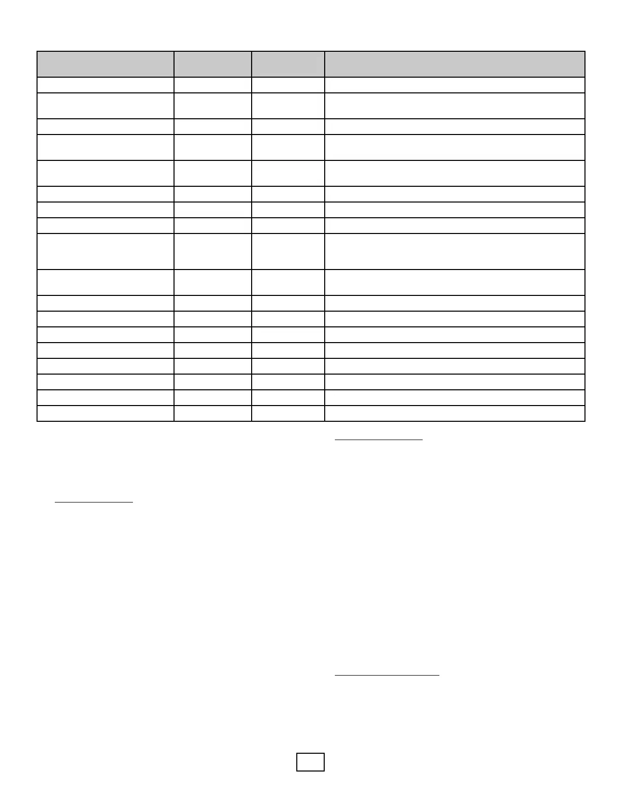
Automac Air Vent, Taco Y 03P017-01BN Install at highest point in system
Boiler Trim Kit Y See Notes
Expansion tank, air separator, automac air vent included;
press. reduc. vlv./backow preventer to be sourced locally.
1" Taco Geo-Sentry Zone Valve Y ATEBV5C One per radiant manifold and one per fan coil
Turbomax indirect water
heater
Y See Notes
Must be ordered with unit as part of unit as 45 or 65 gallon
tank
Brass 3-way valve in cabinet Y 03P016001BN
Two are included with unit. Two more should be ordered for
hydronic piping.
Double O-ring x 1" FPT (pair) Y AGA5FPT Two sets should be ordered for external ush valves.
Boiler drain valve Included 11080003001 Part of plumbing kit
Strainer Included 08P020-01NN Internal to Indoor Module
System Pump Y See Notes
AGSIPV3A (UPS26-115V const. spd. insul. cabinet w/isol.
vlvs.) OR: AGSIPV7A (UPM-XL var. spd. 230V insulated
cabinet w/isol. vlvs.) + AGFCVSC2A controller)
Hydraulic Separator Y ATHS6A
Taco copper separator, 1-1/4” sweat w/mounng brackets,
auto air vent, and blow-down valve
Dierenal bypass valve Y ADBV4A Use on hydronic side of hydraulic separator
Air Handler(s) Y See Notes Review Enertech price books for MPH Series air handers
Radiant Tubing/Accessories Y See Notes Review Enertech price books for Inoor products
Oponal elect. or gas wtr htr Y N/A Supplied by contractor
Pressure Relief Valve Included N/A Included with indirect water heater
Ball Valves Y N/A Supplied by contractor
Unions, adapters, misc. ngs Y N/A Supplied by contractor
Pressure gauge N/A N/A Included with indirect water heater